1. Introduction
Magnesium (Mg) can be recognized as a key element in the human body system. The properties and characteristics of Mg are almost similar to those of human bone. That's why Mg alloys are becoming more prominent as biodegradable implant materials [1]. Because of their superior biocompatibility, Mg alloys were first proposed as an implant material in the field of biomaterials science for orthopedic surgery and trauma in the 1930s [2]. Nowadays, titanium alloys, Co–Cr alloys, and stainless steel are the most frequently used metals in orthopedic applications. They possess excellent strength, durability, corrosion resistance, and load-bearing capacity. But, they cause long-term endothelial dysfunction as they persist in the human body after the lesion has healed. As a result, a second surgery is required when the bone has healed to eliminate the metallic implant material. In this situation, a second surgery prolongs the patients' suffering as well as raises re-hospitalization and healthcare expenses. On the other hand, biodegradable alloys of Mg are novel materials that surpass the whole restrictions of conventional biomedical alloys. In particular, Mg alloys offer a number of advantageous features, including biocompatibility, bioactivity, impact resistance, durability, lightweight, and so on, all of which are very vital in the human metabolic system, and Mg alloys do not require a second surgery to remove the implant because when the bone heals, it degrades automatically due to its biodegradable property [[3], [4], [5], [6]]. The density and mechanical characteristics of Mg, Mg alloys, natural bone, and several metallic implant materials are listed in Table 1.
Table 1. Density and mechanical properties of bone and several implant materials [[7], [8], [9], [10], [11], [12]].
| Materials | Density (gm/cm3) | Modulus of elasticity (GPa) | Tensile strength (MPa) | Fracture toughness (MPa m1/2) |
|---|---|---|---|---|
| Cancellous bone | 1.00–1.40 | 0.01–3.00 | NA | NA |
| Cortical bone | 1.80–2.00 | 3–30 | 164–240 | 3–6 |
| Magnesium | 1.74 | 41–45 | 180 | 15–40 |
| Stainless steel | 7.90–8.10 | 200–210 | 540–1000 | 50–200 |
| Magnesium alloy | 1.75–1.85 | 37.5–65.0 | 135–285 | NA |
| Co–Cr alloy | 8.30–9.20 | 210–253 | 900–1540 | NA |
| Synthetic HA | 3.10 | 73–117 | 100–900 | 0.7 |
| Ti alloy | 4.40–4.50 | 110–117 | 860–965 | 55–115 |
The density, modulus of elasticity, yield strength, and tensile strength of Mg and Mg alloys are almost identical to natural bone. As a result, the stress shielding effect is prevented [13]. In contrast, conventional metallic materials also called non-degradable materials have higher values of density and modulus of elasticity as compared to natural bone. Even though they have corrosion and wear properties, which cause the release of toxic metallic ions and create an extremely dangerous effect on the human body. That is why such types of implant materials are becoming restricted to use in the biomedical field [14,15]. Though, the high rate of deterioration in the physiological condition (pH value in between 7.4 and 7.6) of Mg and Mg alloys, which is a significant challenge for use as an implant material in the human body, cannot be underestimated. This causes the accumulation of hydrogen (H2) gas bubbles under the skin and around the Mg and Mg alloy implants, resulting in the early collapse and loss of mechanical stability of those implants. It might lead to a surgical shortcoming until it can heal, and can also be injurious to the surrounding tissues and body fluids [[16], [17], [18], [19]]. Experts are now investigating a coating approach that might be more successful and safe for moderating the degradation rate of Mg and its alloys. Different modification approaches, like surface treatments and alloying, can be used to reduce the rate of degradation and gas formation of Mg alloys [20]. According to some researchers, Mg alloys, typically containing rare earth elements, tend to be promising for application as orthopedic implants [[21], [22], [23], [24]]. Wong et al. [25] limited the release of magnesium ions by coating Mg alloy (AZ91) with poly-e-caprolactone (PCL) polymer membranes at 2 distinct solution concentrations. In in-vivo and in-vitro conditions it also regulates the degrading rate of the AZ91 alloy. For Mg alloy coating, the coating materials have to be bioactive, biodegradable, non-toxic, and moderate in degradation rate. Some protective coatings are recently being used to mitigate the Mg alloy degradation such as ZrO2, Al2O3, TiO2, and HA. Among these, hydroxyapatite (HAp, Ca10(PO4)6(OH)2) exhibits exceptional bioactivity, biocompatibility, high osteoconductivity, delayed in situ biodegradability, non-inflammatory, non-immunogenicity, and non-toxicity properties and is used in bone tissue engineering applications [[26], [27], [28], [29], [30], [31], [32], [33], [34]]. The HA is mostly composed of calcium apatite and a calcium phosphate (CaP) crystal stage, whose density is 3.16 g/cm3. Basically, it's a type of mineral that makes up the teeth and bone of humans [1]. Berzelius was the first who tried to define the chemical content of CaP compounds in the mid-eighteenth century [35]. Hausen found the distinct phases of CaP crystal and its compositions known as apatite after a century [36]. At ambient conditions, Table 2 summarizes the most frequent CaP salts detected in various stages.
Table 2. Several stages of CaP salts, and their structural formula and atomic ratio [[37], [38], [39], [40]].
| Molecular type | Structural formula | Atomic ratio of Ca/P |
|---|---|---|
| Monohydrate calcium phosphate (MCPH) | Ca(H2PO4)2·H2O | 0.50 |
| Di-calcium phosphate dihydrate | CaHPO4·2H2O | 1.00 |
| Calcium phosphate (anhydrous) | CaHPO4 | 1.00 |
| Monocalcium phosphate (MCP) | Ca(H2PO4)2 | 0.50 |
| α-Tricalcium phosphate (α-whitlockite, α-TCP) | α-Ca3(PO4)2 | 1.50 |
| Fluorapatite (FA) | Ca10(PO4)6F2 | 1.67 |
| Calcium phosphate (amorphous) | Ca8(PO4)6.nH2O | 1.50 |
| β-Tricalcium phosphate (β - whitlockite, β-TCP) | β-Ca3(PO4)2 | 1.50 |
| (brushite, DCPD) | CaHPO4·2H2O | 1.00 |
| Octacalcium phosphate (OCP) | Ca8H2(PO4) | 1.33 |
| Hydroxyapatite (HA) | Ca5OH(PO4)3/Ca10(PO4)6(OH)2 | 1.67 |
The human bone is largely composed of water, collagen and mineral namely CaP, which is mostly biological as well as exhibits osseointegration property [41]. In addition, Ca and P are the primary ingredients of HA, which help the diseased bone tissue healing process. As a result, HA coating offers a significant advantage in biomedical applications for implant applications [42]. But, the use of HA is still restricted to the load-bearing functions because of its inherent brittleness [43]. Moreover, crack free and even surface of HA coating fabrication are still challenging. This study focuses on the features of HA coatings, rapid degradation rate, in vitro fast corrosion and in vivo of Mg and some of its alloys for clinical applications.
2. Recent advanced methodology for HA coating on Mg alloys
2.1. Electrochemical technique
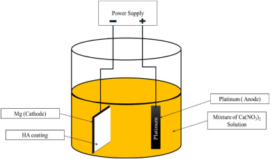
The electrochemical coating technique is one of the most prominent coating approaches which is usually used in the formation of HA coating on Mg and its alloys. The homogeneity of the thickness of the coated layer across the substrate is one of the significant aspects of this method [44]. Before being entirely coated, surfaces of Mg alloys must go through a succession of electrochemical stages. In this process, ions are transported between the cation and anion sides via the potential difference between the anodic and cathodic poles of an electrical circuit [45]. Electrophoretic and electrolytic deposition are popular in HA coating process. Huge suspension particles were found depositing in the electrophoretic method inside the electrolyte, whereas the electrolytic method deposits small amount of materials. In the single coating technique, the above two processes can be regarded as distinct pathways [46,47]. Using an electro-deposition approach, Jamesh et al. [48] established a HA coating on a pure Mgsubstrate at 27 °C in an electrolyte mixture of 0.06 M (NH4)3PO4, 0.1 M Ca(NO3)2, and 10 mL/L 30 vol % H2O2 as well as a pH of around 4. The as-deposited substrates were submerged in a 1 M NaOH solution at 80 °C for 120 min to create a HA coating on the pure Mg substrate, a homogeneous flake-like crystal formation was detected, that could enhanced the biocompatibility. The methodology for electro-deposition of HA coating on an Mg plate specimen is depicted in Fig. 1.
 Fig. 1. Electro-deposition coating demonstration for HA.
Tomozawa et al. [49] employed a hydrothermal treatment on the Mg surface to generate HA coating on Mg substrates using KH2PO4 and Ca-EDTA solution at 60 °C. The mixed crystal structure of HA such as plate-like and needle-like were found. The main advantage of plate-like structures is to offer more surface area that lead to prolong corrosion reaction and increase degradation resistance. The construction sequence of HA crystal structures on the Mg surface is represented in Fig. 2.
 Fig. 2. Schematic diagram of the mechanism of the HA structure on the Mg surface [50].
Fig. 2(a) Indicates the increased pH value causes rapid precipitation of HA crystals on the surface of the Mg specimen as well as the formation of a Mg(OH)2 coating layer. The corrosion rate is higher in this case. To enhance the nucleation of HA crystal formation, Ca2+ ions are consistently supplied to formation of Mg(OH)2 film. A dome-shaped crystal structure could be recognized as an outcome of the periodic nucleation of HA crystals, as illustrated in Fig. 2(b). Due to the thick coating of the Mg substrate with dome-shaped HA crystals, the corrosion rate is considerably lower than the prior one. As demonstrated in Fig. 2(c) and (d), a wire-like or rod-like HA structure has been produced on the Mg substrate varying the pH value of the solution. Positive outcomes of the electro-deposition technology include uniform coating thickness, complex coating shape, the ability to operate at room temperature, and affordability. This approach generates H2 gases on the cathode side, which is a disadvantage. Also, it causes a lot of stress on the coating's surface and shows poor adhesion strength of that coating that lead to create a porous surface [1].
2.2. Sol–gel technique
Nowadays, sol–gel coating might be considered as one of the effective coating methods for biomedical applications. Because it is so consistent, a broad range of research is being conducted in order to obtain adequate performance of the coatings [51]. Two types of sol-gel coating including organic and inorganic sol-gel procedures have been frequently investigated. The organic approach produces a network of suspended colloidal particles with dimensions ranging from 1 to 1000 nm in a steady liquid state. In contrast, the inorganic coating on Mg alloys is fabricated immersing the sample into the solution without forming any chemical reactions [52]. Sol–gel has the ability to overcome the preexisting coating layers' ion release and corrosion issues. It may also quickly fix the porosity of coating layers or structures that is supposed to be degraded. The Sol solution is prepared from calcium phosphorous (CaP) precursors which are mixed with distilled water or ethanol. To enhance the concentration of the aqueous solution to an appropriate standard, the produced mixture is heated at various temperatures. This phase known as sol–gel and it changes phase from a liquid to a gel. The substrates are immersed in this concentrated sol–gel medium after being prepared. This method can be done several times to obtain a multilayered stable coating structure, which is really desired for biomedical applications [53]. A schematic of a sol–gel coating process is depicted in Fig. 3. Rojaee et al. [54] developed nano-structured HA coating on AZ91 Mg alloy using sol-gel coating. The coated surface was parched for the whole day and night at room temperature before being sintered for 6 h at 400 °C. It was found that the coating thickness was appropriately maintained and that the substrate surfacewas completely crack-free and mostly uniform. This approach enhanced cell proliferation, decreased bio-corrosion, as well as promoted bio-mineralization, however it is restricted to the bonding issue between substrate and coating layer.
 Fig. 3. Schematic view of sol–gel coating process [53].
In the literature, an MAO-coating was developed on Mg alloy using the sol-gel method [55]. The sol-gel/MAO coating had a higher density as compared to the MAO coating, and the thickness value was found to be around 8 μm for the sol-gel/MAO coating. When compared to MAO coating alone, the sol-gel/MAO coating technique also ensured an extremely fine, corrosion and micro-pore resistant surface, as well as high electrochemical impedance. SEM images of testing samples have been demonstrated in Fig. 4 for different conditions after 6 h of immersion. At the contact face in between the MAO coating and scratch, having a higher degree of corrosion than that of the sol-gel/MAO coating and scratch. These findings reveal that sol-gel/MAO coating holds greater anti-corrosion properties than MAO coating [55]. Lamaka et al. [56] have used the most popular sol-gel process to develop an anticorrosion coating on AZ31B alloy. According to those researchers, the nanostructured coating surface displayed high anti-corrosion properties as well-conditioned chemical interaction occurs with the Mg alloy. Despite the fact, the sol-gel technique ensures excellent adhesion strength between the coating and substrate, it is inexpensive, operates at a low temperature, and can generate an intricate coating structure. It also does not necessitate the use of any specific vacuum or heating apparatus. But the principal drawbacks of this method are the challenge of maintaining a consistent coating thickness and the very poor resistance to wear because of huge porosity. Furthermore, owing to the rapid evaporation of the solvent and remaining water, the sol–gel coatings are mainly porous with fissures [1,57].
 Fig. 4. Presentation of SEM images of the testing sample for, MAO coating & scratch at (a1), scratch at MAO coating at (a2), sol-gel/MAO coating & scratch at (b1), scratch at sol-gel/MAO coating at (b2), [55].
2.3. p.m.-EDM technique
The acidic biological fluid might cause degradation due to coating adhesion problems [58]. Electric discharge machining (EDM) is one of the most basic, cost-efficient, and productive coating technologies. This EDM is basically used to coat the implant surface with a biocompatible and biomimetic layer to improve mechanical characteristics, corrosion resistance, and bioactivity [59]. Powder mixed-electro discharge machining is a recently developed industrial method. Biocompatible coatings are frequently made from hydroxyapatite powder (HAp), which includes calcium, phosphorus, and oxygen and are applied to biomaterials such as 316 L steel, Ni–Ti, titanium alloy, cobalt alloy, and magnesium alloy [57]. The HA-based EDM coating drastically enhanced the coating performance and provided superior corrosion and wear protection of those biomaterials. The principle of PM-EDM technique shown in Fig. 5.
 Fig. 5. Schematic view of PM-EDM, HA coating approach [60].
While 75 V–350 V of electrical potential is introduced, a 105 V/m to 107 V/m electrical magnetic field is established with a little space between the electrode and the sample. The ionization of the dielectric leads to the formation of a plasma stream. Ions passes through the plasma channel since it is electrically conducting. A distinct electric spark of higher temperature forms in the discharge channel while ions of plasma channel collide each other. This higher temperature causes the nearby powder additives, insulator fluid, electrode, and used sample particles to melt and degrade. Table 3 can be clearly defined as the phase transition of the supplied HA particles due to temperature rises throughout the PM-EDM method [57]. The PM-EDM coating approach for HA coating on the substrate and its penetration mechanism are shown in Fig. 6. The layers are held together in contact between the liquid state of particles and the substrate when they pull against one another, which permits bonding by the electrostatic forces. The approximate adhesion strength and quality of the coating mainly depend on the chemical interactions that take place throughout the PM-EDM process and the features of the coating ingredients [62]. In particular, it is highly essential for bio-implant materials that the adhesion strength of Ca–P-based coatings be at least 17.5 MPa [63]. The surface quality and biocompatibility of Mg alloys such as Mg–Zn–Mn have been investigated by Chander et al. [64] with the EDM technique, and they utilized the HA powder in that process. The mandatory requirement for bone osteointegration was about 5–10 nm in size of Nano porosity of biomimetic bioactive coating, achieved by using 20 g/l HA. This result was found by carrying out a morphological analysis. The layer that was developed on the alloy surface with this PM-EDM technique demonstrated the presence of oxide phases such as Ca–Mn–O, Mn–P, Mn–CaO, Ca–Mg, and Mg–Zn that improved anti-corrosion properties and slowed down degradation behavior [65].
Table 3. The HA state transforms as the temperature rises in the EDM process [57,64,66].
| Range of Temperatures | Phase Transformation |
|---|---|
| 25–600 °C | During the operation, the absorbed liquid (oil or deionized water) vaporizes. |
| 600–800 °C | Reduced carbon presence on the powder surface |
| 800–900 °C | The HAP is coated by an oxyapatite-forming hydroxy-depleted layer |
| 950–1400 °C | Decomposition of hydroxyapatite results in the formation of β-TCP (tricalcium phosphate) and TTCP (tetra calcium phosphate). |
| 1120–1470 °C | At extreme temps, tricalcium phosphate is converted to α-TCP, which is durable. |
| 1550–1630 °C | The melting point of hydroxyapatite is this, and tetra calcium phosphate is also still viable at this temperature. |
| 1650 °C | The TTCP is liquefied and added to the Cao compound. TCP is unaffected. |
| 1730 °C | TCP has been melted. |
| >1750 °C | The formation of amorphous calcium phosphate (ACP) begins. |
 Fig. 6. Schematic exhibition of PM-EDM coating mechanism, [61].
The PM-EDM technique has numerous advantages, including cost-effectiveness, improved mechanical properties, increased wear & corrosion resistance. It also provides a crack-free, bioactive, biocompatible coating surface, and it has the ability to perform simultaneous coating and shaping. But the EDM-generated re-casting layer is often brittle in nature, with fractures, tensile residual stresses, and minor fissures. This has a negative impact on corrosion behaviorand coating fatigue in the respective applications. Sometimes PM-EDMs' high energy intensity causes craters and cracks in the surface. Because of the high temperature, there is a possibility to change the phase of HA. Here, it's also difficult to get the suitable coating thickness and understand the deposition phenomena. These may be considered great issues for this technique [57,67,68].
2.4. PVD technique
PVD is one of the most popular techniques for depositing fine coating layers of different materials on the substrate of Mg and its alloys. It is found that using this method, HA has been mostly studied as a coating material on Mg alloys for its biocompatible and bioactive properties. This technique is usually performed in a vacuum environment. Here, plasma is generated by activating a solid target and depositing it on the substrate of Mg or others. In this approach, the sample material should be positive charges that is accurately positioned in a suitable inert atmosphere. Basically, this plasma is produced due to the clashing interaction between argon atoms and negatively charged target material. On the substrate's exterior surface, this plasma develops a homogeneous covering. There is no chemical reaction between the substrate and the target material. This can be regarded as a positive point for the PVD technique. Another feature of this technique is that the film thickness can be easily controlled [[69], [70], [71]]. The PVD technique for depositing HA coatings is depicted in Fig. 7.
 Fig. 7. Schematic exhibition of PVD set up [72].
There are two types of PVD techniques including sputtering and e-beam evaporation. Where sputtering is the recommended method for Mg alloy substrates. HA sputtered Mg alloys have received the great attention in the biomedical research field. Despite the fact that Al, TO, and TiO2 sputtered Mg substrates have also been examined in various research [71,73]. In a recent work, an RF magnetron sputtering gun was employed as a coating apparatus to create a HA layer with a penetration depth of 500 ± 20 nm on an AZ91 Mg alloy [70]. All such HA-coated samples demonstrated a significant increase in anti-corrosion properties when they were analyzed electrochemically in dissolution medium at 37 °C. These HA-coated samples also exhibited a lower weight loss characteristic than that of the uncoated samples. This result was revealed after immersing these samples in a dissolution medium for seven days. The several layers of HA could be constructed on Mg alloys. This may assist in adequate corrosion prevention. Kiahosseini et al. [71] used an ion beam sputtering technique to generate a HA/ZrN coating on an AZ91 Mg alloy over various periods. The ZrN film was initially formed on the surface of an Mg alloy like AZ91, which was carried out at 400 °C for 2 h with a primary vacuum of 2.3 × 10⁻³ Pa. Consequently, for 180, 240, 300, 360, and 420 min, the HA was accumulated properly at 300 °C under a primary vacuum of 2.3 × 10⁻³ Pa. The film thickness was found to be between 2 and 4.7 m using this method. In comparison to uncoated AZ91 Mg alloy samples, this coated alloy indicates a progression in corrosion behavior. This sputtering technique is often applied to establish various coating layers of biocompatible compounds on Mg alloys in addition to the HA sputtered layer [69,74]. Sputtering coating techniques offer significant corrosion resistance, a strong adhesion force, homogeneous coating surface, thick& pore-less coating, and ease of control over process parameters. However, the major restrictions of this technique are that it is time-consuming, costly, has a poor deposition rate, and has an amorphous coating structure [[75], [76], [77], [78], [79]].
2.5. Micro-arc oxidation technique
Anode spark deposition and plasma oxidation, often referred to as “micro-arc oxidation” (MAO), are essential coating techniques. The fundamental feature of the MAO technique basically depends on an electrolyte that is paired with the proper electrical conditions. In this process, the discharged arc at high pressure and temperature creates a ceramic film on the Mg alloy surface. This makes the surface of Mg alloys almost anti-corrosive with a sufficient hardness [80]. By using MAO methods, Chaharmahali et al. [81] created a Nano-size HA coating on the surface of the AZ31B Mg alloy under various circumstances (5, 10, and 15 g/L). Their primary objectives are to investigate how that Mg alloy with the HA coating behaves in terms of corrosion. The resistance to polarization of the HA-coated Mg alloy is on average 62% greater than that of the uncoated alloy. The corrosion current density was found to be the lowest (1.99 × 10⁻⁶ A/cm2) with a maximum value of positive corrosion potential (−1.54 V) in a concentration of 15 g/L of HA coating. With a HA layer, the MAO approach may considerably improve the substrate's capacity to withstand corrosion. A typical HA particle deposition mechanism on the surface of MAO-coated alloys is exhibited in Fig. 8. HA with composite coating offers superior results than that of single layer coating. The Mg alloy surface was coated with a biodegradable composite coating made of graphene oxide (GO) and HA using a single-step MAO process. A study found that van Der Waals bonding permits the (300) HA plane, which is typically parallel to the surface of graphene, to have an intercellularly strong and long-lasting adhesion. GO can perhaps allow HA grains to make a bond in the MAO coating process simply due to this feature [82]. According to the SEM findings, a HA/GO composite coating might seal off as well as minimize the size of the coating's pores, which are exhibited in Fig. 9. In this case, each of the specimens had open pits/porosity on the tops of their surfaces. In general, the remnant gases are what caused those pits to develop. Due to thermal stresses, they induce micro-cracks on the coated surfaces [83,84]. Surface pits were found to be 11.3%, 8.3%, and 6.7% for the three different concentrations of specimens shown in Fig. 9(a), (b), and (c), respectively. The average bonding strength of natural cortical bone is 35 MPa, but the Mg alloy and coating demonstrated 40.7 MPa, which is superior. According to an electrochemical study, the uncoated Mg alloy revealed two orders of magnitude more than the composite HA/GO-coated alloy. Because the MAO coating and the HA/GO coating exhibited greater polarization resistance than the untreated sample. In particular, the polarization resistance of the HA/GO composite coating is superior to that of the MAO coating, giving it enhanced anti-corrosion properties [85]. MAO techniques have the advantages of being a cost-effective process, being easily controllable, environmentally friendly, and capable of producing intricate coating geometries. The disadvantage of this technique is that it requires appropriate electrolytes and is regarded as a pre-deposition method [64].
 Fig. 8. Typical exhibition of HA deposition on the surface of MAO coated alloy [86].
 Fig. 9. Schematic presentation of SEM images of HA coatings for various concentrations, cross-sections (a–c) and surfaces (d–f) [81].
3. Structure and morphology of Mg alloys with HA coatings for several circumstance
The surface morphology of implant materials with biodegradable properties is highly crucial for tissue engineering. Because the correlation of neighboring tissues with implant materials is highly desirable for active participation of implant and tissue regeneration [87]. The biological properties and coating surface morphology of the implant material can be influenced by basic parameters such as solution pH, doping substances (argentum (Ag), zirconium(Zr), and strontium (Sr)), and the deposition duration as well as temperature. The Sr-doped Zn–Ca–P coating on the surface of the AZ31 Mg alloy greatly improved its biocompatibility and lessened its degrading tendencies [88]. Surface morphology of HA coatings on Mg alloys as demonstrated by SEM images in Fig. 10, after deposition under the specified parameters.
 Fig. 10. Schematic representation of SEM images of HA coatings on Mg alloys (a) at 22 °C, 24 h; (b) at 22 °C, 24 h, polished; (c) at 22 °C’ 48 h; (d) at 22 °C, 2 h; (e) at 30 °C, 1 h; (f) at 50 °C, 1 h, polished; (g) at 50 °C, 1 h; (h) at 30 °C, 0.5 h; (i) at 30 °C, 1.5 h, [89].
Mg alloy samples were submerged in Ca–P solution for 24 and 48 h at 22 °C, but no homogeneous coating formed which are shown in Fig. 10(b–d). The coatings produced were 0.2–0.5 μm thick. In vivo experiments showed fissures forming in the period of homogeneous coating, which may cause implant degradation, as shown in Fig. 10(a). The prepared coatings at room temperature (like 22 °C), require adequate time after 24–48 h of crystallization to crystallize in order to become more consistent. As shown in Fig. 10(f–g), the corrosion rate has gone up at 50 °C due to rapid coating formation. The resulting coatings in Fig. 10(e–i) were much more consistent at 30 °C. The surface morphology of the HA coatings shown in Fig. 10(f–i) found to be desirable based on an in vitro degradation assessment [89]. In a pan of water at 80 °C for 20 min, HA was deposited as reported by Feng et al. [90]. Another study carried out on Mg alloys to develop HA coatings at 95 °C for 6 h [91]. Both tests yielded coatings that exhibit strong corrosion resistance and outstanding bioactivity. Zhang et al. [92] coated AZ31 magnesium alloy for 20 min at 40 °C. That was carried out by utilizing HA powder in the solution of (0.70% weight) phytic acid. They found no fissures and noticed that the layers were not homogeneous. Hence, it might be inferred that it could be preferable to raise the temperature and shorten the time when the HA coating is being applied to the Mg alloy surface. Three different coatings were created for an Mg–Zn alloy by Song et al. [93]. According to their findings, a HA coating was developed by heating up material for 4 h to 80 °C, whereas a DCPD coating was made at ambient temperature, whose pH value was found to be 4.4. This results in quick HA crystal nucleation development with a structure that looks like a flake-shaped. Additionally, at a temperature of roughly 60 °C, a fluoride hydroxyapatite (FHA) coating layer was created. The Mg alloy's surface was then found to have an apatite like crystal structure. The Mg alloy with HA coating sample had several holes and fractures, and in the SBF solution, the structure of DCPD had been dissolved. On the other hand, after two weeks of immersion, the specimen, which is FHA-coated, was found in nearly perfect condition and more homogeneous. The bioactivity for the biological environment and anti-corrosion properties of the alloy were increased by adding an HA coating to an Mg–Zn–Ca substrate which is completely fluoride-treated. Immersion testing and electrochemical analysis confirmed those results [90]. A solution of Ca-EDTA was utilized by Tomozawa et al. [94] to hydrothermally treat the purified Mg to produce a HA coating layer. According to their findings, the pH level of the desired solution highly affected both the structure and crystallographic alignment of the Mg substrates which coated with HA coating, it is as seen in Fig. 11.
 Fig. 11. SEM images showing HA coating on pure Mg at various pH levels: (a) at pH level 5.9, (b) at pH 8.9, (c) at pH 11.9 and (d) at pH 11.9, Following ultrasonic cleaning [94].
The morphological and microstructural conditions of finely polished & pure HA and PCL/HA hybrid-coated Mg–Zn–Ca sample surfaces are shown in Fig. 12.
 Fig. 12. SEM images for: (A) Pure/Untreated, (B) Coating with HA, and (C) Hybrid PCL/HA-coated Mg–Zn–Ca Mg alloy [95].
Fig. 11(a) and (b) show that the morphology of the coating was very fine and homogeneous in its construction. Their corresponding pH values are 5.9 and 8.9. At a pH of 11.9, a pattern like chestnut was detected due to the development of the HA coating, as shown in Fig. 11(c). The very tiniest structure of the crystal was revealed following the ultrasonic cleaning process; which is demonstrated in Fig. 11(d). The authors concluded that, especially in comparison to pH values of 5.9, 8.9, and 11.9, there is significantly more nucleation at pH value 11.9 than that of others. Numerous configurations have been thoroughly studied, including crystal form, crystal planes, as well as the sizes of the HA produced particles and flakes [94,[96], [97], [98], [99]]. In another study, Wang et al. [100] utilized an Mg–Zn–Ca alloy on whose surface they developed a Ca-deficient HA coating layer using the electro-deposition technique and incorporated various surface characteristics. Which are mainly based on the length of the treatment process. As a result, researchers concluded that the heterogeneous nucleationand development of HA crystals strengthened the anti-corrosion properties of that Mg–Zn–Ca alloy. On the Mg alloy surface of Mg–Zn–Ca, M. Rahman et al. [95] created a PCL/HA hybrid coating and compared it to pure and only HA coated Mg–Zn–Ca surfaces. The extremely fine surface shown in Fig. 12(A) was achieved by polishing and grinding. Fig. 12(B) shows a coherent mixture of plate and needle-like structures of crystals in HA coated Mg–Zn–Ca Mg alloy and this ensures better conditions for surface morphology. However, successive layers of PCL/HA hybrid coating make a compact and comparatively thicker surface, as seen in Fig. 12(C). Due to the barrier obtained by this PCL/HA hybrid coated thick layer, the rate of degradation and corrosion in the physiological conditionsis satisfactorily decreased.
4. An overview on characteristics of HA coatings on Mg alloys for several circumstance
4.1. Corrosion behavior
Corrosion performance is one of the critical phenomena used to assess coating stability, coating durability, and surface morphology at several conditions. At physiological environments, HA coating on Mg alloy surfaces is predicted to have good anti-corrosion properties. Because these HA coatings possess outstanding thermodynamic stability by nature [101]. Traditional Mg alloys are not able to handle such issues like lower biocompatibility, high corrosion, as well as lower bioactivity, and this limits their application in cardiovascular devices and orthopedic fields. In this case, an electrochemical depositionapproach was used on the substrate of AZ91D alloy to create a HA coating layer that increases anti-corrosion characteristics, bioactivity, and biocompatibility [102]. The EIS study was performed to investigate the corrosion and degradation rates. It was observed that the produced coating was constituted of DCPD and β-TCP before beginning to convert into HA, which has a lower rate of degradation and corrosion. At 85 °C and a pH of 5, Wen et al. [103] used a perfect mix of different electrolytes like 0.1 mol/L NaNO3, 0.025 mol/L NH4H2PO4, and 0.042 mol/L Ca(NO3)2 with a 60-min immersing time to produce a HA coating on the Mg alloy AZ31. Then, at 80 °C, NaOH solution was used to immerse the coated Mg alloys for 4 h, followed by 4 h of drying at 60 °C. At the as-deposited state, the Mg alloy HA coatings had a radiating plate-like pattern, and after post-treatment, they had a needle-like structure. The SEM images of the AZ31 alloy in SBF solution with uncoated and HA-coated conditions 7 days later are shown in Fig. 13.