1. Introduction
With the help of digital technology, technological advancement is bringing the world to a new level [1]. Numerous technological advancements, software and hardware capabilities, and workflows are all happening at rapid pace [2]. Platform evolutions such as cloud technology and the effect of the Internet of Things (IoT) are presently driving the adoption of a universal access system to provide fast and effective innovation, flexible resource, advanced online security and scalability [3]. According to author's, computer-aided design (CAD) technology is continuously evolving to keep up with the changing environment [4]. AI based simulations offer a better solution with less effort in spite of the internal parameters of the system under work [5]. For example, in a simulation, meshing is the most time-consuming and error-prone task. Most meshing tools disregard the parametric information and merely mesh the model's border representation. As a result, each time a parametric modification is implemented, the model is essentially re-meshed from the initial concept, which occurs several times during the design process. Moreover, the size of mesh is also another factor while meshing. Abbasi et al. (2020) [6], discovered the impact of mesh size in conventional friction stir welding (CFSW) and underwater friction stir welding (UWFSW) in their examination of thermal and mechanical characteristics of Al6061-T6 utilizing a three-dimensional computational finite element technique. Deform-3D software was used to simplify a high amount of mesh distortion during friction stir welding due to strong plastic deformation processes [7]. In general, getting the perfect meshing takes a long time. However, with the latest developments like SimSolid [8], it is now possible to get simulations right away. SimSolid enables quick design iterations since it generates simulations without meshing. This reduces the time required to perform simulations by eliminating the requirement to employ local mesh control in more strained places [9]. It is capable of doing same analyses as other commonly used finite element analysis (FEA) tools [10]. ANSYS Discovery live tool can produce simulation results in real-time [11]. As fast as you can rotate the model, one can edit the geometries and see stress results. Instant CAD tool can perform simulations on the part being analyzed, and can give simulation results instantaneously [12]. This can increase productivity through waste reductions. According to studies, CAD can be used to its full potential to increase productivity and work quality by integrating with emerging modern technologies.
The present paper focuses on the use of AI in CAD, as well as the use of CAD in extended reality and 3D printing. Artificial Intelligence (referred as ‘AI’) has spanned a wide range of fields as a result of its potential applications, as evidenced by numerous academic papers and practical applications [4]. AI uses quantitative reasoning, simulation, and deep modeling [13]. Some of the application areas of AI are evaluating component images from its production line in real-time, improving worker safety, reducing costs, designing new products in real-time, and etc. [14]. In extended reality (i.e. virtual reality (VR), augmented reality (AR), and mixed reality (MR) in this paper context), simulation results takes place in a 3D environment thereby providing an opportunity to view objects in three dimensions [15,16]. The technology of extended reality is not limited to academic research; they have sprung up to a new industry [17]. In a variety of virtual reality disciplines, researchers have achieved tremendous progress [15]. They are widely used in space travel [18], which is fraught with high costs and risks. Another significant application of CAD is in 3D printing technology. 3D printing is an additive manufacturing (AM) process, which involves the layered production of 3D solid objects directly from CAD models without the aid of part-dependent tools, and has been used to fabricate complex and high-precision objects in many fields [19]. It revolutionizes manufacturing because of its unique ability to print complex shapes and produce an accurate system [19]. However, as of present, there will be no 3D printing without the application of CAD. Hence, the application of CAD in the industries is emerging tremendously.
In general, creating an intelligent design environment necessitates the development of numerous software with computational and analysis features. In this paper, the future of CAD with AI, extended reality, and 3D printing is reviewed. The main objective of this review is to evaluate the importance of integrating AI into CAD systems and investigating the application of CAD in extended reality and 3D printing technology, and its future prospects.
2. Future prospects of CAD
2.1. Artificial intelligence (AI) application in CAD
Previously, the term ‘artificial intelligence’ is used to describe machines ability to mimic human intelligence through learning and reasoning during complex problem solving [13,20]. Many AI researchers have recently challenged this approach, characterizing AI in terms of rationality, which does not limit how intelligence may be characterized [21]. Intelligent machines reason and make decisions independently and without error in accordance with their design or pre-set program [22,23]. In recent years, companies have been able to establish an efficient and effective intelligent CAD environment by incorporating AI into their systems [24]. Incorporating AI into the CAD system will reduce the lead time dramatically and creates knowledge-based design environment. In hospitals, AI-based CAD is being utilized in a clinical practice alongside a picture archiving and communication system (PACS) to improve workflow [25]. For green manufacturing and sustainable development, the integration of AI with a variety of technologies is currently in great demand [26].
The necessity for integrating AI into design was recognized early in the CAD development process. Mann (1965) [27] proposed some conjectures on intelligent design at the early stage of CAD development. Brown and Chandrasekaran [28], explored the issues of the hierarchical structure of knowledge representation and problem-solving strategy in routine engineering design. Rao et al. (1989) [29], and Rao et al. (1993) [30], have put forward the main areas on which intelligent design researches are concentrated. According to their report, intelligent design system research fields include small scale intelligent design systems, wide areas intelligent design systems (through coupling), intelligent computation and analysis, and intelligent graphics interface. An intelligent graphics interface equips existing CAD systems with many tools that can improve the accuracy and precision of designs, hence increasing productivity and work quality [31]. However, building an intelligent design system has remained a hot research study until now. Panarotto et al. (2020) [32], established a method for producing varied concepts of CAD modelsbased on the combination of function modeling and CAD. The method uses the newly proposed object model for function and geometry (OMFG) to relate the product's design concept to design automation (DA). According to their report, the purpose is to help product developers explore a larger section of the design space during the early stages of product development by taking into consideration the geometric domain and the functional domain. Miller et al. (2018) [33], expanded the CAD model to include product attributes and behavior, to use information that was previously available in separate applications for the digital twin. Heikkinen et al. (2018) [34], discovered seven distinct techniques for using CAD-models as transdisciplinary information carriers. They were; extra characteristics, name, parameters, annotations, packed features, programmed features, and additional geometry. Schulz et al. (2018) [35], demonstrated how Pareto-optimal (a group of designs that are optimum for multiple trade-offs, rather than a single optimal design) may be utilized to navigate performance trade-offs in computer-aided design (CAD) models.
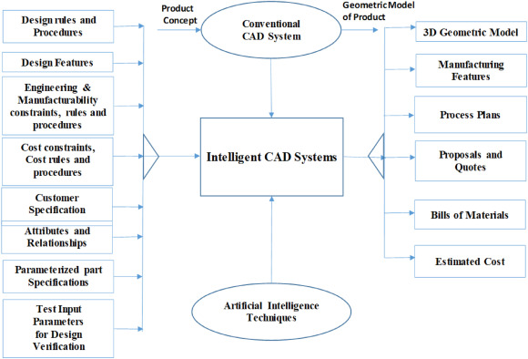
Fig. 1 indicates how conventional CAD can be converted into intelligent CAD systems. The process of merging CAD with AI is called model-based reasoning (MBR). By using the quantitative and qualitative analysis, it predicts the interaction that could exist between different parts of the design [36].
 Fig. 1. CAD into intelligent CAD [31].
Features of MBR:
-
–
The product parts should be stored in a hierarchical manner in order to know their relationship
-
–
It is the designing experts who provide the knowledge-based reasoning and decision-making procedure
-
–
The reasoning and the methodology define the rules for links of product parts
-
–
The cumulative analysis of the qualitative and quantitative simulation defines the efficiency of the product analyzed
-
–
Easy installation procedure in the database
2.1.1. Some examples of CAD software's integrated with AI application
2.1.1.1. SOLIDWORKS xDesign
Dassault Systemes Company, owner of SOLIDWORKS software, is one of the leading companies that have integrated AI into its design product [23,37]. The company introduced xDesign that use AI as a tool to draw and extrude in engineering design works. In SOLIWORKS xDesign, operators can deploy different solutions to their design challenges instantaneously through cloud collaboration that are generated by AI tool. First, the operator creates the model and defines the constraints. Then after, SOLIDWORKS xDesign will generate the part instantaneously through AI integrated to its system based on the constraints defined by the user [38].
2.1.1.2. NETVIBES One Part
NETVIBES One Part is another AI driven design software introduced by Dassault Systemes Company. The tool provides an intuitive application to reuse already existing parts to safe time. In NETVIBES One Part, operators can get 2D/3D related parts by just a few clicks [39].
2.1.1.3. Artificial intelligence (AI) denoiser
Artificial intelligence Denoiser is AI tool created by NVIDIA and use AI and machine learning to provide instantaneous interactive feedback to users for better decision [40]. It uses GPU-accelerated AI to create visually noiseless image at ultra-fast speed. At present, AI Denoiser is the fastest and easiest image visual rendering tool existing to date [39].
2.1.1.4. Generative design
Generative design is another AI user developed by AUTODESK. Generative design will lift AI to change tedious design processes into a sophisticated ones [41,51]. The method is done by changing the parameters randomly with-in already defined boundary to generate a set of distinctive designs based on a built-in parametric CAD system [42]. Khan and Awan (2018) [36], proposed a space filling generative design technique (GDT) which integrates a computer program (Jaya Program) and CAD for the creation of innovative designs. According to their design, a CAD model m can be represented by n number of design parameters x_(m,1), x_(m,2), x_(m,3) … x_(m,n). Fig. 2 shows different alternatives of 3D CAD model for ceiling lamp using generative design by considering space filling and non-collapsing criteria.
 Fig. 2. Design alternatives for a 3D ceiling lamp CAD model; space filling and non-collapsing criteria added [36].
2.2. CAD application in extended reality (VR, AR and MR)
Since the advent of CAD systems, it was made possible to see three dimensions of the product before its manufactured. At present day, CAD models are being used beyond 3D modeling. Simulating effects and work scheduling is being done with CAD. Kinematic relationship that helps to verify functionality and collision avoidance can be done in CAD software. However, there is still a gap in that CAD applications do not provide immersive visualization and interactive simulations, such as that seen in extended realities (Virtual Reality (VR), Augmented Reality (AR), and Mixed Reality (MR)). There are many intricate pro-cuts in the real world that require detailed conceptualization before being made. It's tough to mimic real 3D world with traditional CAD technologies. However, in extended reality technology, the model created in CAD software is loaded into VR, AR, and MR platforms for immersive simulation and detailed conceptualization.
2.2.1. Virtual reality
Virtual reality (referred to as “VR”)) technology is a type of virtual simulation that uses a computer simulation to generate and experience a virtual world of a real system [42]. Users of virtual reality technology are fully immersed in the environment during simulation. The two typical characteristics of VR are immersion and interaction. Currently, VR is upgraded to use a variety of sensors (eye recognition, voice, gestures and brain waves) and multi-dimensional information environment interaction, combined with interaction in the real world [43]. The virtual reality simulation applications have also extended from class room education to military trainings [44]. Streusand et al. (2010) [45], reported the use of VR for novel decision making in the area of robotics. Regassa (2020) [46], designed and simulated 6° of freedom robot manipulator using a VR tool called ‘Virtual Universe Pro’ software. According to their report, the 3D model of the robot manipulator is first created by SolidWorks, CAD software, and then the complete motion of the system is programmed and controlled by PLC (Programmable Logic Controllers) programming. According to Luo Jun et al. (2016) [47], VR allows students to have a better understanding of the subject matter, especially when a visual representation of the real process is required. In the health sector, virtual reality technology is being used to support procedural training, diagnosis, and to give virtual therapy in times of emergency [48,49]. In the aviation industry, VR is frequently used for a range of applications, including cabin design [50] and pilot training [52].
The challenge of CAD optimization for VR is that the kinematic relationship created in CAD programs will not be available after being imported to VR platforms. For instance, Lorenz et al. (2016) [53] has tried to develop a methodology to avoid this issue using special software like digital content creation (DCC) systems. They have mentioned three different options of converting CAD to VR as given in fig 3. Option 1 is on the basis of VR collaboration and 1:1 scale. In option 2 and 3, the animation is saved on virtual reality modeling language (VRML) file.
 Fig. 3. Transmission of motion data and kinematic relationship to VR [53].
2.2.2. Augmented reality
Augmented reality (referred to as “AR”)) is half virtual and half reality computer technology [54]. Augmented reality is a kind of real-time computing that uses the position of the camera images combined with the corresponding image from the same angle [55]. The goal of AR technology is that the set of the virtual world on the screen created has to interact in the real world. According to Shea (2011), in AR, data display in the physical object can be enhanced by providing dynamic information overlay [56]. Lai et al. (2020) [57], introduced a worker-centered system comprised of multi-modal AR instructions backed by a deep learning network for tool recognition to reduce time and error in an assembly operation. According to their report, the dataset was built using CAD tool models and shown in a two-dimensional environment without the usage of real tool pictures. Brandt et al. (2021) [58], developed a user-friendly and intuitive user interface to improve AR assembly assistance adaptability. Neb et al. (2021) [59], developed a method for fully automating AR assembly assistance using 3D assembly models. According to their technique, assembly data is extracted from a CAD model, and processed on a server, and then sent to a Microsoft HoloLens 2 via two independent user interfaces. At the University of Washington, Phillip Dunston and his team have presented the initial concept of AR CAD that can support construction and design [60]. According to their report, the AR CAD system is an integration of AR assistant viewer into standard CAD to provide good intuitive interaction with models designed [60]. The AR CAD system consists of a computer for CAD modeling, a computer that can run and view AR and HMD (head-mounted display) with a camera attached to it.
2.2.3. Mixed reality
Mixed reality (referred to as “MR”) is the further development of virtual reality technology [15]. It is the technology developed through the introduction of reality in the virtual environment. Since the MR technology involves both virtual and real objects, it will enhance the sense of understanding for better experience [61]. The visual composting and blending, one of the important factors in MR, requires an understanding and analysis of the real object [62]. In the field of game technology, the engaging and funnies of MR technology has helped it gain more attention [63]. The system of mixed reality usually adopts the three main features:
-
1.
It is a combination of virtual and reality
-
2.
In the virtual three-dimension (3D registration)
-
3.
The real-time operation
Fig. 4 describes the relationship between Virtual reality (VR), Augmented Reality (AR) and Mixed Reality (MR) form the view point of real environment and virtual environment.
 Fig. 4. The relationship between Virtual reality (VR), Augmented Reality (AR) and Mixed Reality (MR).
2.3. CAD application in 3D printing: integration of design and manufacturing
One of the practical applications of CAD is in a 3D printing technology. In 3D printing technology, the 3D object model must first be created in the appropriate size and dimensions, and then saved as CAD file using CAD software. A CAD file includes instructions or rules that govern 3D printers. It determines how much material must be deposited and where it should be placed. The saved CAD file is transferred to the 3D printer for processing. The technology of 3D printing produces parts or objects by adding a layer by layer based on the parameters in the CAD file. It is also called additive manufacturing[64]. Unlike the subtractive manufacturing systems, it doesn't require complex set-ups, coolants, or other supplementary things. It is very cost effective and efficient especially for single parts and small batches [65]. It can produce complex objects that are very difficult to produce with the conventional machining system [66]. Fig. 5 shows the different types of 3D printing techniques now in use in industry [67,68]. The usage of CAD for three-dimensional product design and modeling is unavoidable in all scenarios of 3D printing technology.
 Fig. 5. 3D printing techniques [68].
Fig. 6 figuratively describes the process of 3D printing in FDM using Geomagic as CAD software and Slic3R as CAM component [69]. According to Gibson et al. (2015) [69], after the object is 3D printed, there are post processing operationsapplied on the object to increase the quality of the product.
 Fig. 6. The process of 3D printing in FDM [69].
2.4. Application areas of 3D printing technology
Today, there are a variety of 3D printing applications that take advantage of the flexibility provided by CAD tools to generate any type of design or 3D model. The following are the major application areas of 3D Printing.
2.4.1. Micro/nanoscale 3D printing
3D printing technology is being utilized to manufacture micro/nanoscale parts based on the pre-designed CAD model [70]. 3D printing technologies that can manufacture at micro/nanoscale includes; two photopolymerization reactions [71,72,and73]], direct ink writing (DIW) [74,75,79], electrohydrodynamic printing (EHDP) [76], and projection microstereolithography (P SL) [77,78]. So far, numerous advantages have been achieved in manufacturing metamaterials, MEMS [64], biosensors [80] and lab-on chips [81] using these techniques.
2.4.2. Aerospace industry
In aerospace industry, 3D printing technologies are widely utilized [82,83]. Superior parts can be optimized using CAD tools and 3D printed rapidly. Currently, broken aerospace parts are also being repaired with the aid of 3D printing techniques. Fig. 7 shows blisk repair with the aid of a 3d printing technique called laser engineered net shaping (lens).
 Fig. 7. a) T700 Stage 1 blisk after LENS leading edge repair b) Blisk after finishing [84].
2.4.3. Automotive industry
Similar to aerospace industry, automotive industry requires high quality, low cost, specialized components that need CAD modeling and rapid prototyping. The model designed on CAD software can be 3D printed rapidly in automotive industries. In 2014, the first electric car called “Strati” was manufactured using 3D printing technology [85]. Fig. 8 shows a steering axle produced by Rennteam Uni Stuttgart using direct metal laser sintering (DMLS) technique [86].
 Fig. 8. Rennteam Uni Stuttgart steering axle using DMLS [86].
2.4.4. Medical application
In the medical area, at present, the applications of CAD tools are widely used in the advancement of medical devices and implantations [87]. After first modeling the object in CAD tools, it was made possible to manufacture medical devices, bionics, prosthetics, orthodontic and orthopedic implants, and other medical equipment's using 3D printing technology [68,88]. Fig. 9 shows 3D printed tissue product starting from medical imaging.
 Fig. 9. 3D printed tissue product [88].
2.4.5. Solar energy
In the solar energy area, solar cells are being manufactured with 3D printing technology. Vak et al. (2015) [89], have used 3D printer assisted slot-die coater to print perovskite solar cells. Dijk et al. (2015) [90], 3D-printed a saturated acetone vapor smoothened concentrator array for external light trapping on thin film solar cells. Ahn et al. (2009) [91], used a 3-axis micro positioning stage to print flexible and stretchable silver micro electrode for solar cells. James and Contractor [92] used fused deposition modeling (FDM), extrusion-type 3D printing, to create a fractal-based counter electrode (CE) for dye-sensitized solar cell (DSSC) in a cost-effective way. They modeled the leaves of Camellia japonica (Japanese Camellia) plant for the DSSC CEs using the commercial CAD software package – CATIA V5. Micro-reactors, solar concentrators, components for solid oxide fuel cells, and implants are being fabricated using fused deposition modeling [[93], [94], [95]], streolithography [96,97], selective laser sintering [96], and direct ink writing [97,98].
2.4.6. Nanotechnology
In a nanotechnology, 3D printing and nanotechnology provide a tremendous amount of advantages in altering material character jointly [99]. Williams et al. (2018) [100], have used two photon lithography (TPL) techniques for the fabrication of magnetic nanostructures. TPL is a 3D printing technique that can produce features less than 150 nm [101]. Gaga et al., 2022 [102], used 3D printing technology to develop the nano satellite cube enclosure able to collect data on an altitude of 40 km. To examine drift characteristics of sensor, a flexible temperature sensor made up of silver nanoparticles (Ag NPs-PEDOT: PSS) is printed using inkjet printing [103]. Laser sintered inkjet printing is used to print Ag NP inks to create highly conductive patterns with a resistance of 3.5/cm2 [104]. For small-scale operations, 3D printing techniques are employed to create structural catalysts for the conversion of syngas to ethanol that overcome mass and heat transfer restrictions created during the brazing process [105].