1. Introduction
The urgency for stringent standards on criteria pollutants and greenhouse gases (GHGs) is well understood. The effects of climate change have been accelerated by human activity over the last century. The transportation sector alone has accounted for around 16% of global CO2 equivalent (CO2eq) emissions in 2016, from which 12% was due to road transport [1].
To respond to both climate and human health concerns, many countries have emission and fuel economy regulations in place for passenger cars and commercial vehicles. Two good recent reviews of these standards and the technologies used to meet them are provided in [2,3]. These emission standardshave been progressively tightened over the years in an attempt to reduce criteria pollutants such as oxides of nitrogen (NOx), carbon monoxide (CO), unburned hydrocarbons (UHC), and particulate matter (PM). For example, NOxemissions from gasoline-fueled passenger cars were regulated at 0.15 g/km under the Euro 3 standards starting in 2000. In 2005, the regulation tightened to 0.08 g/km under Euro 4, and once again to 0.06 g/km in 2009 starting with Euro 5. It has been suggested that under the upcoming Euro 7 standards this value should be further reduced to 0.03 g/km [4]. A similar reduction in other criteria pollutants can also be seen over the years: CO standards for gasoline engines tightened from 2.3 g/km for Euro 3 to 1.0 g/km, starting with Euro 4. CO standards will be further tightened for Euro 7, as early as 2025. One proposal calls for CO regulations as low as 0.1 g/km for Euro 7 [4]. Such stringent emission regulations, along with the rising price of the platinum group metals(PGM) used in three-way catalytic converters, require automakers to suppress the engine-out raw emissions and optimize the aftertreatment systems with low PGM content. Furthermore, since Euro 6d enacted in 2021, the particulate number (PN) emission has been limited as 6 × 10¹¹/km under real driving emission tests, with a conformity factor of 1.5. The PN regulation put further pressure on automakers to adopt gasoline particulate filter (GPF), which inevitably needs regeneration and increases back-pressure that deteriorates the fuel efficiency.
In addition to criteria pollutants, the EU will continue to tighten CO2 tailpipe regulations to help meet the goals of the Paris Agreement. The EU has set an EU fleet-wide target of 59 g-CO2/km for the average emissions of new passenger cars, a nearly 40% reduction over the current standard of 95 g-CO2/km, to be achieved by the end of this decade. It is also under discussion to add methane and nitrous oxide (N2O) to regulated GHGs as part of the Euro 7 legislation [3].
It is quite fascinating to see (from an engineering point of view) how the engine development community has answered the call to reduce emissions under these ever-tightening standards. Emissions regulations have resulted in the development of novel technologies that increased brake thermal efficiency (BTE) (thereby reducing CO2 emissions) and reduced criteria pollutants. In recent years, electrification has become a useful technology to reduce regulated tailpipe emissions1. Conway et al. [3] predict that the battery electric vehicle(BEV) could reach a 50% global market share by 2040 if the current adoption rate is maintained. Nevertheless, current market indicators suggest that the internal combustion engine (ICE) will still be a major contributor for years to come in the various market segments [3].
For heavy-duty sector, Conway et al. [3] identified some key directions engine manufacturers have recently used to increase BTE while meeting emission standards. For example, there is an increase of the peak firing pressure, optimization of fuel-air mixing and the air path, use of exhaust energy recovery, reduction of friction forces through lubricants, and the use of new piston designs. For light-duty vehicles, Senecal and Leach [5] listed downsizing, exhaust energy recovery and high compression ratio as some ways used to increase BTE. Similar technological advances need to be made to meet future emission standards like Euro 7/VII. Advances in engine aftertreatment (AT) technologies such as electrically heated catalysts to reduce cold-start emissions [6], dual urea dosing system for diesel aftertreatment [7], or the use of urea/SCR for gasoline NOx compliance are some of the important developments towards achieving these standards.
Numerical modeling of ICE processes has proven invaluable in the search for novel technologies to increase efficiency and reduce harmful emissions. From air flow in the manifolds, to fuel-air mixing in the cylinder, to combustion and emissions formation, computational fluid dynamics (CFD) has complemented and sometimes even led test bench experiments. The unique capability of CFD in shedding light on these complex processes that are unreachable by traditional test bench experiments has helped researchers to understand and solve many barriers when it comes to increasing efficiency and reducing emissions. This paper will later bring forth several such success stories from industry-leading OEMs to support this fact. It is also quite important to stress the value of test bench experiments. The numerical predictions are only useful if they are properly validated against accurate and timely measurement data. Hence it is the authors’ view that CFD and experiments should be used in a complementary fashion in the search for future technologies to meet global emission standards.
This paper will look at the contribution of CFD in the industry's search for novel powertrain technologies to develop Euro 7/VII vehicles. Given how strict the upcoming regulations look to be, these technologies will likely be a mix of advanced combustion concepts, cleaner fuels, advanced aftertreatment systems, and electrification. The ability of the CFD tools used by powertrain designers to model these key concepts is important in meeting Euro 7/VII emission standards. The paper will show how CFD has been used successfully in the past (and is used now as well) to model complex ICE and aftertreatment related phenomena and how these simulations have resulted in increased BTE and reduced emissions. Even in zero tailpipe emission BEVs, CFD is used regularly to design fuel cells, batteries and electric motors. The paper will discuss these aspects in detail as well.
2. Role of CFD in enabling new emission reduction technologies
CFD plays an important role in aiding researchers by increasing their understanding of the important processes in an engine. CFD is a valuable tool in searching for new fuels (discussed in Section 3) and engine systems (discussed in Section 4) that will help meet future emission standards in the short, medium, and long term. Most light-duty vehicles today run-on gasoline fuel and use spark ignition (SI) engines [2]. CFD can be used effectively in many areas of the SI engine from fuel injection and fuel-air mixing to ignition and combustion through flame propagation. CFD can also be used to investigate the formation of emission species like CO, HC, NOx, and soot emissions from SI engines. CFD plays an equally important role in the design of compression ignition (CI) engines that are commonly seen in heavy-duty vehicles. CFD can help find technologies that reduce soot and NOx emissions simultaneously. Not only is CFD helpful in shedding more light into the processes that generate emissions, but it also can help design emissions aftertreatment systems such as selective catalytic reduction (SCR) and lean NOx traps, and gasoline and diesel particulate filters. This paper will bring forth examples of how CFD has been used to obtain a deeper understanding of the processes that have been optimized to increase fuel economy and reduce emissions from light-duty and heavy-duty engines.
In an interview, Eiji Nakai, the general manager of the Mazda powertraindevelopment division stated the importance of numerical simulations in developing the Mazda SKYACTIV-X engine, which is claimed to be 20-30% more efficient than a conventional Mazda gasoline engine at the time of its development [8]. In this blog post, Eiji Nakai explained how simulations have helped them optimize input conditions in their gasoline-fueled, spark-controlled compression ignition (SPCCI) engine to account for the wide-range of driving conditions. It also describes how CFD-based model development has helped Mazda reduce their design cycle time compared to the traditional prototype build/test-based method. The blog post explains that with the new SKYACTIV-X engine Mazda clients can enjoy the driving performance of a 2-liter gasoline sports car with the CO2 emissions of a 1.5-liter diesel car (Mazda 2). This illustrates how CFD modeling can be leveraged to design engines that can meet current and future emission standards.
Another recent demonstration of CFD-aided powertrain improvement is the Cummins Super Truck II program. The program achieved an impressive 55% BTE in a heavy-duty diesel engine equipped with a waste heat recovery system. The information given in [9] indicates that CFD was used to achieve cleaner combustion strategies with multiple fuels. It also shows how genetic algorithmswere used to optimize the piston bowl shape to increase BTE and minimize gross indicated specific fuel consumption (GISFC) with constraints on NOxemissions, PM emissions and peak cylinder pressure. Indeed, CFD-driven genetic algorithms have been used to optimize engine designs for over two decades with great success [10].
Toyota Motor Corporation [11], [12], [13] presented how CFD was used to develop the world's first gasoline engine in volume production that achieved a maximum thermal efficiency of 40% in 2016. This engine, named ESTEC 2ZR-FXE, powers the fourth-generation Prius and incorporates various advanced technologies to improve combustion characteristics, knocking, heat management, and friction losses. Cooled exhaust gas recirculation (EGR) technology was combined with optimized valve timings, refined exhaust and intake manifold layouts, and a high-energy ignition coil system, leading to lowered exhaust pumping loss, improved scavenging performance, uniform EGR distribution between cylinders, and stable combustion [11]. While the cooled EGR is effective in mitigating knocking, the reduced combustion rate by diluted mixtures was compensated with increased in-cylinder turbulence intensities. Comprehensive geometry analysis and optimization for the piston top surface and the intake port were carried out, and as a result the tumble ratio was dramatically elevated from 0.8 to 2.8 [12]. CFD was utilized to calculate in-cylinder flow characteristics for a number of port designs, and find a set of optimum valve and port angles that increase tumble ratio while retaining the high flow coefficient. The increased turbulent intensity by high tumble ratios effectively shortened the combustion duration (mass fraction burned from 10% to 90%), which extended the EGR limit and hence greatly reduced fuel consumption [13].
Senecal et al. [14] present how high fidelity CFD can be used to accurately predict NOx emissions from heavy-duty diesel engines (Fig. 2.1). The ability to numerically model and predict criteria pollutants is important when finding strategies to reduce them.
 Fig. 2.1. NOx emissions comparison from CFD predictions against measured data for different start of combustion (SOC) values in a heavy-duty diesel engine.
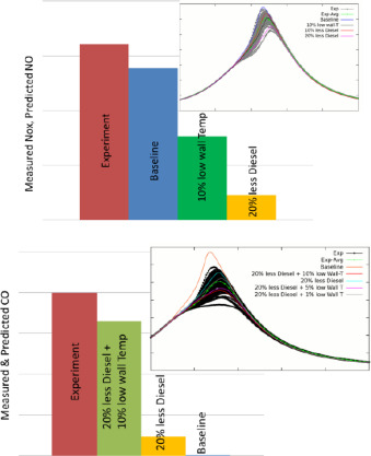
CFD provides a unique tool for engineers and researchers to evaluate novel emission reduction strategies at a lower cost. Wijeyakulasuriya et al. analyzed at NOx, CO, UHC, and soot in a large bore heavy-duty natural gas and diesel dual-fuel engine [15]. After comparing predictions with measurements, they evaluated the input parameter uncertainties and how they affect emission species formation and oxidation as shown in Fig. 2.2. It can be seen that the CFD is capable of carrying out “numerical experiments” into various control parameters of the engine in search of strategies to lower emissions.
 Fig. 2.2. Comparison of NOx (left) and CO (right) emission predictions from different numerical parameter changes against measured data.
Fuel absorption and desorption in lubricating oil are one of the main sources of HC emissions in SI engines [16]. CFD models can provide detailed information about the fuel spatial presence in the cylinder and fuel mass in the piston-liner crevice. Furthermore, newly formulated models can be implemented into CFD to model this phenomenon through user defined functions, which enables fast implementation of cutting-edge features.
3. Role of CFD in finding new fuels to reduce emissions
More than 95% of the fuel used for transportation today is provided by liquid fossil fuels [5]. Burning these fuels is a major source of GHG emissions that contribute towards climate change. If alternate “cleaner” sources of fuel were substituted for these carbon-based fossil fuels, ICEs could continue to drive the future of transportation. Developing such cleaner fuels would be instrumental in meeting any future emission regulation.
Clean fuels, including low carbon content, carbon neutral or carbon negative, are fuels that produce much lower GHG emissions than traditional fossil fuels on a well-to-wheel basis. There are biofuels (such as cellulosic ethanol), renewable diesel, synthetic fuels, and ammonia, as well as gaseous fuels such as clean hydrogen (H2) and renewable natural gas. Clean fuels are produced from a variety of feedstocks, such as agricultural and forest biomass, and waste materials. Senecal and Leach [5] stated how these cleaner fuels can be used in existing ICEs with little or no modification. This is an important aspect when it comes to widespread adaptability for these fuels to become commercially available
CFD, along with detailed chemistry modeling, can help simulate the energy release and emission production from these different types of fuels in ICEs. This helps to understand how different fuels (oftentimes a blend of pure fuel components) behave differently under varying drive conditions. CFD can be used to simulate how certain fuels film more under cold-start conditions, how higher volatile components evaporate to reduce ignition delays, and how oxygenated fuels help reduce emissions. CFD can show the researchers how differential evaporation of fuel components make fuel stratification inside the cylinder and how this affects the fuel burning and subsequent pollutant formation. For example, in a natural gas and diesel dual-fuel engine, Wijeyakulasuriya et al. [15] showed that early injection of diesel results in diesel moving outwards and starting to ignite at the cylinder liner. Hence, contrary to a flame propagating from the center of the chamber and moving outwards, they observed a flame moving inwards towards the center.
Jha et al. [17] showed that the onset of both low- and high-temperature heat release of n-dodecane (the chemical surrogate used for diesel) is delayed by the presence of methane in their natural gas and diesel dual-fuel engine. They also confirmed that diesel started igniting before methane. A comparison of predicted engine-out NOx, CO, and HC (Fig. 3.1) to measured values at three different diesel injection timings (The firing TDC in this work is taken as 360 deg CA) gives confidence that emissions trends can be reasonably captured. They identified that some CH4 was trapped in the piston crevices and remained unreacted which contributed to the CO and unburned HC emissions (Fig. 3.2). This demonstrates the value of CFD when investigating different types of fuel blends in existing engine hardware.
 Fig. 3.1. Engine out NOx (left) unburnt HC (middle) and CO (right) emissions at three different start of injection (SOI) values for 80% methane and 20% diesel fuel blend.
 Fig. 3.2. Partial combustion near cylinder crevices shown using the time evolution of mass fraction of CH4 (left) and CO (right).
Nowadays there is a renewed interest in using H2 to power ICEs. Using H2 in an ICE is not a new idea, in fact the first ever ICE, the “de Rivaz engine,” ran on H2back in 1806 [5]. With modern direct injection hardware and engine boosting technologies, H2 can be used more effectively in ICEs despite its low power density. In 2022, Srikanth Padmanabhan, Vice President and President of the Engine segment at Cummins stated: “Our hydrogen-fueled engine development program is one of our latest steps to advance zero-carbon technology. It looks very promising and I am excited about the capability of a hydrogen engine to virtually eliminate CO2 emissions. A model year 2027 Class 8 sleeper cab semi, powered by a hydrogen ICE would generate 144 fewer metric tons of CO2 per year versus its diesel-powered counterpart” [18]. Of course, only burning so-called “green H2” made from renewable electricity will reduce carbon emissions to a greater extent from the use of these engines. A review of the many colors (i.e., production methods) of H2 is provided in [5].
The use of H2 poses several modeling challenges to CFD with its low density, high mass diffusivity in air, wide flammability range, high burning velocities, and low ignition energy. Modeling H2 injection and combustion can be challenging in terms of simulation run time. Direct injection of H2 accompanies with very high gas velocities, of which maximum value can reach supersonic. Resolving the high-velocity needs small grid sizes, which accordingly reduce the time-step size due to the CFL number limit, and thereby the total computational cost for memory and runtime increases substantially. Another challenge in simulating H2 combustion is the high flame speeds. Again, resolving the fast-moving reaction front with high burning velocities requires finer meshes and smaller time steps. Accurately modeling the binary or mixture-averaged molecular diffusion is also important in this simulation to obtain accurate flame speeds. This requirement increases the simulation time for transport calculations. On the other hand, since H2 has low ignition energy, H2 trapped in chamber and piston crevices can burn when they enter the combustion chamber during the latter part of exhaust blow-down. If the engine is dual-fuel and the intake charge carries another fuel, this undesirable post-burning causes a risk of flame flash back into the intake port during valve overlap. Modeling all these complex phenomena can be challenging and expensive in CFD. All of the above factors about H2 pose a fire hazard and safety issues that the engineers need to account for, for which accurate numerical tools can contribute immensely. The numerical tools used will be able to aid the engineers in designing new devices to suppress undesirable flame flashback into the intake port which in turn will help them use H2 as a fuel to reduce carbon emissions. In order to avoid engine backfire, direct injection (DI) of H2has been proposed. However, DI of a fuel like H2 at very high-pressure introduces challenges in the CFD modeling of the mixture formation process [19]. It has been shown that CFD can be instrumental in understanding mixture formation in a real engine and designing advanced injector nozzle geometries that can maximize efficiency and minimize emissions [20].
Quenching distance/diameter is another important quantity when it comes to designing safety features used in engines that are fueled by highly reactive fuels like H2. Quenching distance is the dimension of a channel/tube below which a propagating flame would not go into. With channel diameters below the quenching diameter, the heat loss from wall heat transfer dominates the heat generation from the flame. Hence the flame is quenched. The ability of CFD to predict flame quenching distances accurately for different fuels, is an important consideration when using CFD to design next-generation ICEs that will meet future emission standards like Euro 7/VII.
When using CFD tools to model ICEs with alternative/renewable fuels, having access to accurate fuel oxidation chemistry is of paramount importance. Heywood [16] summarized the importance of chemical kinetics modeling to ICE emission predictions in this way: “The concentrations of pollutants in ICE exhaust differ from values calculated assuming chemical equilibrium. Thus, the detailed chemical mechanisms by which these pollutants form and the kinetics of these processes are important in determining emission levels.” Accordingly, the availability of fuel and pollutant chemistry is key to engineers trying to design ICEs with novel fuels (H2, ammonia) and fuel blends (biodiesel, biogasoline, E10, E85). Dong et al. [21] recently published a new surrogate fuel mechanism which has fuel chemistry for C0-C4 fuels, hexane isomers, n-heptane, iso-octane, nC8-nC12 linear alkanes as well as chemistry for polycyclic aromatic hydrocarbons (PAHs) and NOx as pollutants. Researchers and engineers can now extract the fuel and pollutant chemistry for the species they want to study in their ICE which is going to be a subset of this published mechanism. For example, if an engine is to be tested with natural gas and H2, one can extract fuel chemistry for C0-C4. If an engine is to be tested with ammonia (NH3) and diesel, then fuel chemistry for C0-C7 can be extracted assuming n-heptane to be the fuel surrogate for diesel. Then this extracted mechanism can be further reduced to retain fuel chemistry that is important for NH3 and nC7H16 oxidation while matching ignition delay and/or laminar flame speed within user-specified tolerances. A validated global kinetics mechanism like this is going to be quite useful in future pursuits of emission reduction from ICEs. This mechanism [21]also includes chemistry for oxygenated fuels such as methanol and ethanol. Methanol is a popular e-fuel under consideration and the availability of fuel chemistry for such e-fuels and biofuels will undoubtedly aid CFD modeling of these renewable fuels in ICEs.
NH3 is another attractive alternative to fossil fuels2. Compared to the very low energy density of H2, NH3 has an energy density comparable to fossil fuels while being carbon-free. Ammonia has a higher autoignition temperature and a lower laminar flame speed which means that it is relatively difficult to get ammonia to start burning and to complete the burning process quickly, once the flame is established. However, it has an octane number of 110 which means that it is more knock resistant. Yousefi et al. [22] recently studied NH3 and diesel dual-fuel in an ICE in order to test the viability of reducing GHGs. They carried out both experimental and numerical investigations on a single-cylinder, heavy-duty diesel engine with varying amounts of ammonia substitution. They found that increasing the NH3 energy fraction from 0% (diesel only operation) to 40% retarded the start of combustion while increasing the first heat release rate peak (premixed spike). They attributed the delay in combustion to the higher ignition delay of NH3 while the higher first peak was due to an increased amount of fuel burning as premixed combustion. They were able to come to these conclusions by looking at fuel-air equivalence ratio, OH mass, and temperature inside the cylinder. This work demonstrates the ability of CFD to explain the reasons behind novel fuel burning behavior. They were also able to lower the CO2 emissions by 12%, NOx emissions by 10%, and CO emissions by 20% by using NH3 and diesel dual-fuel, compared to diesel-only operation. This study again highlights the importance of using CFD to model alternative fuels to reduce ICE emissions.
4. Role of CFD in model and method development for efficient engine design
Developing a new engine that satisfies emission regulations with an improved thermal efficiency requires substantial time and cost. However, with the high-computing resources, CFD simulations can perform virtual design and testing in batch as an alternative to fabricating a few prototypes and testing them with limited measurements. Furthermore, CFD simulations can provide fundamental understanding and guide engine design and control strategies through a quantitative analysis of in-cylinder processes. However, one can capitalize on the above-mentioned advantages from CFD simulations only if the results are accurate.
An engine runs under transient and steady states with widely-varying load and speed conditions. Since the current emission regulations employ either test cycles or real driving emission (RDE) tests to measure and limit the cumulative emissions, CFD models need to be accurate for a range of engine operating points. Moreover, CFD simulations need to retain the predictive performance as much as possible for the design of advanced engine combustion concepts. In general, high-fidelity CFD simulations can be accurate but are computationally expensive. In this regard, high-fidelity models with affordable computational cost would be beneficial for virtual engine development.
By far, the engine modeling community has developed numerous CFD models and derived optimization techniques with machine-learning (ML) algorithms. In this section, instead of providing a comprehensive review of all the historical advancements in CFD models and methods, we will present the state-of-the-art model development for selected in-cylinder phenomena in Section 4.1, and the novel method development which focuses on engine design optimization and tool efficiency improvement in Section 4.2.
4.1. Model development
4.1.1. Spark-ignition engines
In gasoline direct injection (GDI) engines, air-fuel mixture distribution greatly impacts the subsequent combustion and pollutant formation processes. Krämer et al. [23] reported that 99% of all injection processes during the New European Driving Cycle and 95% during the RDE test are under superheated conditions in mid-range cars. Flash boiling of fuel spray occurs at sub-atmospheric pressures in the cylinder or at high fuel temperatures, and several experimental research studies demonstrated that flash boiling improves the fuel atomization but leads to spray collapse and lengthens spray penetration [24,25]. A CFD model that accurately captures flash-boiling phenomena would better predict the air-fuel mixture distribution at the time of ignition compared to standard spray models, thus helping engineers to correctly optimize the injection strategy in the engine development process.
Several researchers have modeled and tested two main aspects of flash boiling: phase change and atomization. For the phase change, Senda et al. [26] and Adachi et al. [27] have developed a vaporization model for flash boiling, that accounts for bubble cavitation, heat transfer at the gas-liquid interface, and superheating of liquid fuel. The developed model showed good agreement with experimental data in terms of droplet diameter and vapor mass fraction. On the atomization aspect, Zeng and Lee [28] proposed a secondary breakup model consisting of two competing mechanisms of aerodynamic force and bubble growth. The droplet under superheated conditions would break up by bubble growth, which sheds smaller child droplets than by aerodynamic force alone. Later, Price et al. [29] and Duronio et al. [30] employed Zeng and Lee's model and extensively validated it by using experimental data obtained under relevant in-cylinder conditions. The model was able to reproduce the collapsed spray structure and the penetration length and droplet sizes compared to the measured data.
Injected liquid fuel can impinge on the combustion chamber walls, and the spray-wall interaction (SWI) induces a locally fuel-rich mixture near the walls (also known as fuel film wetting) and greatly affects the particulate emissions. Köpple et al. [31] showed that the particulate number decreased by more than one order of magnitude when the piston surface temperature increased by 25-30 K. Also, Choi et al. [32] reported that a GDI engine emitted more than 70% of particulate emissions during the cold-start phase, due to increased wall wetting. Therefore, CFD simulations should accurately capture SWI processes to predict the air-fuel mixture and fuel film deposition to support the optimization of fuel injection strategies.
Several SWI models were developed and used in engine CFD simulations[33–35]. Recently, Torelli et al. [36] developed an SWI model with a novel method for impingement frequency calculation to improve droplet splash predictions. The developed SWI model was validated against experimental data and demonstrated improved predictions in spray rebound radii and height compared to existing SWI models. Also, the authors incorporated a wall roughness model to the developed SWI model, by which they were able to reproduce realistic recirculation and shape of the rebounded spray leading edge.
After the air-fuel mixing, spark ignition takes place to initiate the combustion process. Some modern GDI engines using cooled-EGR or Miller/Atkinson cycles incorporate a tumble-intensified intake port that significantly increases the turbulent intensity around the spark plug at the time of ignition [13]. Spray-guided GDI engines adopt late injection strategies for some operating points to secure stable ignition, which induces high-velocity crossflow near the spark plug [37] that would impact the spark channel behaviors and cause spark-channel elongation, blow-outs, and re-strikes [38]. On the other hand, retarded spark timing used in the catalyst heating phase is needed to maximize the exhaust enthalpy for catalyst light-off while maintaining low cycle-to-cycle variation. Since most of the tailpipe emissions are generated during the cold-start phase, due to low conversion efficiencies of three-way catalytic converters(TWC) [39], the optimization of engine controls including ignition timing is crucial for emission reduction. Thus, ignition models need to be predictive for the entire engine operating range to develop a more efficient and cleaner engine system.
Many SI models have been developed in the past few decades, among which the most relevant ones are the Arc and Kernel Tracking Ignition Model (AKTIM) [40], Discrete Particle Ignition Model (DPIK) [41], Spark Channel Ignition Monitoring Model (SparkCIMM) [42], and Imposed Stretch Spark Ignition Model (ISSIM) [43]. Recently, Scarcelli and his coworkers [44,45] developed a LESI (Lagrangian-Eulerian Spark-Ignition) model and coupled it with various combustion models that have been widely used in SI engine CFD, such as G-equation [46] and the Thickened Flame Model [47]. The LESI model demonstrated the compatibility for the tested combustion models and also for different turbulence modeling frameworks (RANS and LES) while generating reasonable simulation results compared to the experimental data. D’ Adamo et al. [48] improved the ISSIM (Imposed Stretch Spark Ignition Model) formulation by considering the thermal expansion and high stretch of the flame kernel, and they investigated cycle-to-cycle variation (CCV) of SI combustion under fuel-lean conditions. The model reproduced the measured data in terms of substantial increment in CCV when the air-fuel mixture became ultra-lean. A spark model developed for highly efficient dilute engines was implemented in Moiz et al. [49]. The spark model predicts the energy transfer from the electrical circuit to the combustion chamber gases. A 1D sub-model was used to predict the instantaneous flame kernel size. The developed model was able to predict ignition and misfire for moderate and high EGR with modest and high flow conditions.
Engine knock is one of the main limiting factors to achieve maximum brake torque timing, so spark timing needs to be adjusted to maximize thermal efficiency while avoiding severe engine knock. On the other hand, an end-gas auto-ignition event with precise combustion phasing controls can be utilized to reduce the combustion duration and improve thermal efficiency [50]. Hence, CFD simulations need to predict such auto-ignition physics and simulate advanced combustion concepts accurately and efficiently.
Robert and his coworkers [51,52] proposed a CFD model framework combining Extended Coherent Flame Model (ECFM) and LES [53] and Tabulated Kinetics of Ignition (TKI) [54] models to simulate turbulent flame propagation and auto-ignition in a boosted SI engine. The model framework was able to match the measured cylinder pressures, coefficient of variation (COV) of indicated mean effective pressure (IMEP), and knock onset spark timing. Furthermore, they analyzed the autoignition regimes of knock and super-knock using pressure waves and autoignition heat release observed in LES results. Yue and Som [55]developed a CFD model framework that combines the G-equation model and the transported Livengood-Wu integral approach [56] to predict the knock-limited spark-advance (KLSA) in a boosted GDI engine. The developed model was able to predict the KLSA within 2°CA for various operating conditions, and the authors found that the benefit through charge cooling and knock mitigation is marginal. For modeling mixed-mode combustion, Xu et al. [57] developed a hybrid G-equation and well-stirred reactor model based on the large eddy simulation framework. The simulation results well matched the measured data for heat releases by both flame deflagration and auto-ignition, as well as the cycle-to-cycle variation in combustion characteristics.
GDI engines emit more particulate emissions than PFI (Port Fuel Injection) engines [58]. Due to the direct injection of liquid fuel, SWI is inevitable and the late evaporation of fuel-film during the combustion process significantly contributes to the particulate emissions [59]. Hence, the optimization of injector designs and fuel injection strategies are crucial in developing engines that comply with stringent PN emission regulations.
Jiao and Reitz [60] developed a CFD model framework to simulate soot formation in a GDI engine, where a chemical mechanism with polycyclic aromatic hydrocarbon (PAH) reactions was directly solved in each computational cell to predict pyrene formation, and an improved soot model based on a multi-step phenomenological modeling approach was used to calculate the soot mass and number. Kim et al. [61] developed a simulation framework by incorporating a laminar flamelet library and a method of moment soot model, where concentrations of PAHs (up to coronene) computed from a detailed chemical mechanism were subjected to a nucleation process with low computational cost. The developed model framework was validated against the experimental data for predicting the changes in soot number and mass densities with respect to the changes in injection pressure. Recently, Fontanesi et al. [62] developed a soot library using 0D constant pressure reactor simulations and coupled it with a sectional method to predict the soot emissions in a GDI engine, including the particulate size distribution (PSD). The model was able to simulate the ultrafine PN changes according to the injection timing variation and also qualitatively capture the PSDs compared to experimental data.
4.1.2. Compression-ignition engines
In diesel engines, the rate of air-fuel mixing mainly governs the subsequent combustion and pollutant formation processes. Therefore, injector and piston bowl designs and injection strategies need to be optimized to achieve high efficiencies and low emissions. Numerous CFD models have been developed for liquid spray processes: primary breakup [63], [64], [65], secondary breakup [66], [67], [68], vaporization [69,70], inter-collision [71,72], and SWI [33], [34], [35], [36]. It is worth noting that many of these models have been applied to both SI and CI engine simulations, and only the recent model development for CI engines will be discussed in this section.
Within the Lagrangian-Eulerian framework for spray modeling, momentum transfer between the liquid droplets and the gas flow is calculated by using a droplet drag coefficient. Unlike conventional approaches assuming a perfectly spherical droplet [69], Dahms and Oefelein proposed a Corrected Distortion (CD) model [73] that considers droplet non-sphericity effects for drag and evaporation formulation, where the Taylor Analogy Breakup model [66] was used to estimate the transient droplet distortion and oscillation. Nguyen et al. [74] recently implemented the CD model into the CONVERGE software and extended the CD model validation against experimental data obtained from relevant engine conditions.
Conventional diesel combustion can be seen as a spray flame process with high turbulence-chemistry interactions, for which the unsteady flamelet approaches [75,76] has been widely adopted in the CI engine modeling community. In modern CI engines, multiple injection strategies are employed to lower NOx and PM emissions and reduce combustion noise (i.e., control pressure rise rate). To this end, Felsch et al. [77] extended the two-dimensional (2-D) representative interactive flamelet (RIF) equations [78] using a ‘collapsed-flamelet’ scheme and enabled simulations for any number of split injections in CI engines. For a CI engine running with three injections (pilot, main, post injection), they were able to match the measured pressure curves and heat release rates. On the other hand, Kim et al. [79] reduced simulation turnaround time about 80% in CI engine simulations by implementing a modified 2-D RIF model [80], and they were able to match the measured heat release rate traces and the NOx and PM emissions for triple and quadruple injection strategies under various engine load and speed conditions.
Pachano et al. [81] utilized the improved flamelet solver in an unsteady flamelet progress variable model to predict soot processes, in which the computational cost of CFD simulation was reduced by approximately 40 times compared to a non-tabulated well-stirred reactor modeling approach. Also, the simulation results were able to reproduce the measured soot volume fraction trend, especially in the soot ramp-up region. These studies directly show the benefit of accurate and predictive CFD models in reducing engine out emissions which is crucial in meeting any future emission standards.