1. Introduction
Composite structures have emerged as a pivotal and innovative solution in the field of civil and structural engineering, offering advantages over traditional construction materials [1]. These structures combine the unique properties of different materials, such as concrete, steel, and fiber-reinforced polymers (FRP), to create high-performance systems that exhibit superior strength, durability, and resilience [2], [3]. The increasing demands for sustainable, lightweight, and cost-effective infrastructures have motivated engineers and researchers to explore composite materials' potential extensively [4], [5]. The use of composites allows for the optimization of structural designs, enabling the construction of longer spans, taller buildings, and more efficient bridges. Moreover, composite structures offer exceptional resistance to harsh environmental conditions, corrosion, and seismic forces, ensuring enhanced safety and longevity. As the world faces new challenges in urbanization and the revitalization of aging infrastructures, the integration of composite materials into civil engineering practices becomes a driving force in shaping the future of sustainable and resilient construction [6], [7].
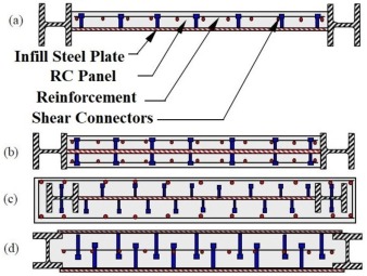
Various forms of composite structural systems and components have been developed and used in the past decades [8], [9], [7], [10]. Composite shear walls are among these applications of composite materials in construction. Composite shear walls are innovative types of lateral load-resisting systems that consist of steel and concrete components, and may also include other materials (such as wood [11] or Fiber-Reinforced Polymers (FRP) [12]). The steel-concrete composite shear walls can be broadly categorized into two categories: Concrete-Encased Steel shear Walls (CESW) [13] and Concrete-Filled Double-Skin steel shear Walls (CFDSW) [14]. While different names have been used in the technical literature to describe the first category, including Buckling Restrained Steel Shear Walls (BRSW), Concrete-Encased Composite Plate Shear Walls (C-PSW/CEs), and also Composite Steel Plate Shear Walls (CSPSW) (based on the first introduction of this structural system in the AISC seismic designprovisions [15]), this review paper will refer to them as CESW. Fig. 1 shows the common variants of steel-concrete composite shear walls.
 Fig. 1. Common variants of steel-concrete composite shear walls [13]: a) CESW with one-side RC panel; b) CESW with both-side RC panels; c) embedded CESW; d) CFDSW.
CESWs can be seen as a modification of Stiffened Steel Plate Shear Walls (SPSWs) and have been approved by various structural design codes such as CAN/CSA-S16-01 [16] and AISC-341/16 [17]. These composite walls consist of an infill steel plate encased on one or both sides with reinforced concrete panels, as shown in Fig. 1a and Fig. 1b. The development of CESWs as a lateral load-resisting structural system is motivated by their advantages over traditional steel and reinforced concrete shear walls, including:
-
•
CESWs can provide the same shear strength and stiffness as RC shear walls with smaller thickness and weight, which is beneficial from both an architectural and seismic design standpoint.
-
•
The shear yielding of the infill steel plate in CESWs, prevented from buckling by the RC panels, results in a much higher capacity than the tension field action in steel plate shear walls.
-
•
The RC panels also provide sound and temperature insulation and reduce the system's vulnerability to fire compared to steel plate shear walls.
-
•
The use of precast RC panels can increase convenience during the construction phase.
-
•
CESWs, especially those with a gap between the RC panel(s) and boundary elements, experience reduced necessity for retrofitting and rehabilitation after a moderate or frequent earthquake, as damage is usually limited to shear yielding of steel plates with minimal cracks in the RC panels or damage to other system elements [13].
Over the past two decades, various studies have been conducted on different types of composite shear walls, with multiple systematic reviews being performed, mainly on CFDSWs. Some examples of these reviews are the ones by Ali et al. [23], Hilo et al. [24], Mo et al. [14], and Alatshan et al. [25]. However, in the case of CESWs, there are very limited reviews that are not as comprehensive as the ones mentioned above. Furthermore, these limited studies were carried out before 2016, when the number of published research on CESWs was still very small. One of the earliest review studies on CESWs was conducted by Zhou et al. [26]. In this study, the authors reviewed several papers on composite steel plate shear walls, including both CESWs and CFDSWs. However, most of the reviewed research was written in the Chinese language. Another state-of-the-art review of the CESW system was performed by Ćurković and Džeba [27], who reviewed some of the studies on this system up until 2016.
The purpose of this study is to conduct a comprehensive and up-to-date literature review on CESWs to provide a clear understanding of the current state-of-the-art and the main findings related to this structural system. A comprehensive state-of-the-art review of CESWs holds significant importance and motivation in the field of civil and structural engineering, particularly in the context of high-rise and low-rise buildings. CESWs are increasingly recognized as efficient lateral load-resisting systems that can enhance the seismic performance and structural integrity of buildings. As urbanization continues to drive the construction of tall and slender structures, the demand for effective and robust lateral load-resisting systems becomes crucial to ensure the safety and resilience of buildings under seismic and wind forces. CESWs have emerged as a promising solution due to their ability to combine the advantageous properties of steel and concrete, offering enhanced stiffness, strength, and ductility. However, despite their potential, there is a need for a comprehensive review to consolidate and synthesize the existing research on CESWs. By undertaking such a review, the study aims to provide a clear understanding of the current state-of-the-art, identify research gaps and contradictions, and explore potential future research directions. Ultimately, the outcomes of this review will contribute to optimizing the design and analysis of CESWs, fostering safer and more efficient building construction practices in both high-rise and low-rise contexts. The review aims to highlight the present research gaps and contradictions between the reported results by different researchers, as well as identify potential future research directions. The study attempts to cover most of the major published research works on CESWs to provide a concise yet thorough overview of the advances in the design and analysis of this type of structural system.
The structure of this paper is organized as follows: Section 2 describes the methodology employed for paper collection and the selection criteria utilized for choosing the papers included in this review. Section 3 to section 7 provide a comprehensive overview of various configurations and variants of Confined Earthbag Wall Systems (CESWs). Based on their overall configurations and performance characteristics, CESWs are classified into five distinct groups, namely traditional CESWs, embedded CESWs, CESWs with slotted infill plates, CESWs with partial connections of infill plates, and multi-panel and modular CESWs. Each configuration is introduced, highlighting its advantages and objectives, followed by a summary of studies conducted on that particular system. These studies are categorized into three subsections based on their type: experimental, numerical, and analytical. In cases where a reviewed paper encompasses multiple types of studies, each part will be discussed within the relevant subsection. Furthermore, unique or special types of studies conducted on each configuration will be discussed within their respective subsections. Section 8 provides a comprehensive summary and classification of the reviewed studies, incorporating informative diagrams and tables to facilitate understanding. Section 9 presents the identified existing research gaps and potential contradictions between reported results and accordingly outlines future research directions for CESWs. Finally, Section 10 presents concluding remarks, summarizing the main contributions of this paper.
2. Literature review methodology: scope and criteria
This review provides a comprehensive overview of the performance and design aspects of Composite Encased Shear Walls (CESWs). To collect relevant research literature, an extensive search was conducted in the Scopus database using five main keywords: “Composite Shear wall”, “Concrete Encased Shear wall”, “Stiffened Steel Shear Wall”, “Composite Steel Plate Shear Wall”, and “Buckling restrained steel shear wall”. Initially, a total of 504 documents were identified. To refine the search results, several filters were applied, including a publication date range from 1990 to 2022, consideration of only articles as source types, and inclusion of journal articles and review papers as document types. Additionally, only documents published in the English language were considered. After the initial filtering and exclusion process, the search results were narrowed down to 251 documents.
A two-phase screening process was then implemented to further refine the results. In the first phase, screening was based on the title and abstract, resulting in a reduction of manuscripts from 251 to 146. In the second phase, a full-length screening was conducted, resulting in a further reduction to 93 references. Finally, after conducting an in-depth review of the selected papers, 14 additional references were excluded due to various reasons, such as low quality of the publishing journals, significant overlap with the other papers, insufficient information about the methodology, or inadequate presentation of results. Consequently, the final selection consists of 79 journal papers, which will be reviewed in the following sections. Section 8 of this review will provide detailed and summarized classifications of the final selected documents, offering a comprehensive overview of the relevant literature.
3. Performed studies on traditional CESWs
Although CESWs have been used since 1964, the initial studies on the CESWs in the current form considered by design codes were conducted by Astaneh-Asl and Zhao [13], [28], [29], as mentioned in Section 1. Based on their early research, a typical CESW is composed of several components. The main components of a conventional CESW are depicted in Fig. 2.
 Fig. 2. Schematic representation of the main components of a CESW [13].
Typically, a steel plate with a thickness of not less than 10 mm is used in CESWs to provide shear strength and resistance through shear yielding, as per code requirements [17]. Thinner plates are not recommended because they can be difficult to handle during fabrication and erection. Moreover, research has shown that very thin plates need a large number of shear connectors to ensure that the yielding of the plate happens before its buckling [13]. Various steel grades can be utilized for the infill plate; however, steel grades with lower yield strength are preferred since they ensure the shear yielding of the plate.
In a CESW, RC panels are utilized at one or both sides of the infill plate, which can be cast-in-place or precast. These panels play a crucial role in the system by providing lateral bracing to prevent the steel infill plate from buckling before its yields in shear. Additionally, the RC panel assists in carrying a portion of the story shear by developing a compression diagonal field. Shear connectors are essential components that ensure the composite behavior of the system. The shear connectors primarily sustain shear loads, but they may also be subjected to tension actions due to the buckling of the infill plate. The type of RC panel used (cast-in-place or precast) determines the type of connectors, such as shear studs, steel channels, or bolts, that are employed. It is important to note that the shear connectors should be designed to avoid failure and to enable the infill plate to yield in shear prior to other failure modes.
The boundary beam and column are essential components of the CESW system, serving as an anchor for tension field action in the infill steel plate and a bearing element for the diagonal compression in the RC panels. In addition, the boundary columns contribute to resisting applied overturning moments and can transfer part of the story shear, particularly for large-size columns. The boundary beams experience a large shear flow at their end due to the overturning moment, and the type of beam-to-column connection may vary depending on whether a single CESW or a dual lateral load-resisting system, i.e. CESW and moment-resisting frame, is employed. The connection between the infill steel plate and the boundary elements is crucial for transferring the shear forces, and bolts or welds can be used for this purpose. The reinforcements of the RC panels may also be connected to the boundary elements.
Astaneh-Asl and Zhao [28], [29] proposed a modified configuration for traditional CESWs, which includes a gap between the RC panel(s) and boundary elements (as shown in Fig. 3). This configuration results in the RC panels not participating in resisting applied lateral loads until the gap between them and the boundary elements is closed. Consequently, under relatively small lateral drifts, the system behaves similarly to stiffened steel plate shear walls, and the role of RC panels is limited to providing out-of-plane bracing for the infill steel plate. However, under large displacements and after the gap is closed, both the steel plate and RC panels provide strength, stiffness, and ductility for the system, with the participation of the RC panels adding additional stiffness compensating for the stiffness loss of the infill steel plate due to yielding. The researchers also suggested filling the gaps with elastomeric materials to further enhance damping and energy dissipation in the system.
 Fig. 3. An schematic view of the so-called innovative CESW [13].
In the following subsections, the performed studies on these traditional configurations of CESWs will be reviewed based on the type of study, i.e., experimental, numerical, and analytical.
3.1. Experimental studies
The performance of traditional CESWs has been investigated by various researchers through experiments. In the following subsections, these studies will be reviewed:
3.1.1. Overall performance
As mentioned previously, the first experimental study on CESWs was conducted by Astaneh-Asl and Zhao. They tested two 1:2 scaled, two-and-a-half-story, single-span specimens with one-side RC panel (with and without gap) cyclically [13], [28], [29]. It should be noted that the first publication was a report by Professor Astaneh-Asl about their performed tests and some design recommendations to the Structural Steel Educational Council (SSEC). The other two papers also reported the same experimental results. It is noteworthy that the mentioned report is the background for the design requirements of CESWs in AISC 341 [17].
Based on their observations, Zhao and Astaneh-Asl [28] reported the hysteresisand cyclic performance of both types of CESWs. They found that the presence of the gap in the system improved ductility and reduced the damage to the RC panel(s) in relatively large displacement cycles. Their experiments showed that the contribution of the RC panel in the novel CESWs to the total strength and stiffness of the system was below 20%. It was also shown that CESWs behaved in a very ductile manner and were able to provide a drift ratio of 5% before the shear strength dropped below 80% of the peak shear force.
In addition to their experimental findings, Zhao and Astaneh-Asl [28] provided some design recommendations based on their study. They suggested prioritizing ductile failure modes over brittle ones and designing the wall system to ensure that ductile failure modes occur before brittle ones. They recommended avoiding tension fracture and compression buckling of the boundary columns to prevent stability issues and high repair costs after earthquakes. Furthermore, they proposed ignoring the strength of the RC panel for conservative design but suggested considering its stiffness in calculating the system's period of vibration. They also recommended using the design requirements of special moment resisting frames for the boundary element, with a web thickness at least equal to that of the infill plate. Finally, they suggested that the shear connectors should collectively be able to transfer the shear capacity of either a steel plate or a reinforced concrete wall, whichever is smaller.
To validate their developed numerical models, Rahai and Hatami [30] tested three small-scale specimens of CESWs with the gap. These specimens were used only for validation of their performed numerical study, which will be further explained in subsection 3.2.1.
Arabzadeh et al. [31] conducted a comprehensive experimental investigation on one- and three-story CESWs with a gap between the RC panel and the boundary elements, at 1:3 and 1:4 scales, respectively. Their study is one of the most detailed and comprehensive investigations of CESW performance. They reported on the overall cyclic behavior of the system and examined the effect of different parameters, including the beam-to-column connection of the boundary frame, on the overall performance of the system. The study was conducted in two phases, and a total of 13 CESWs were tested, including 5 single-span single-story CESWs with hinged beam-to-column connections, 4 single-span single-story specimens with moment-resisting frames, and 4 single-span three-story CESWs with moment-resisting frames. The specimens were cyclically loaded according to the guidelines of ATC-24 [32]. The experimental program in this study was designed to investigate the influence of different parameters, including the number, thickness, and reinforcement details of RC panels, the thickness of the infill plate, the type of beam-to-column connections, the details of the infill plate connection to the boundary elements, the effect of the gap, and the spacing of shear connectors, on the overall cyclic performance of the CESW system. It is worth noting that RC panels with thicknesses of 30 mm and 40 mm were used in this study. In their conclusion, the authors noted that the minimum RC panel thickness and reinforcement bars were sufficient, but did not mention their basis for calculating these minimum values. They also suggested design recommendations for the proper design of boundary elements using AISC guidelines [17] and assuming the total shear yielding of the infill plate.
In another experimental study, Yu et al. [33] investigated the Performance of CESWs and compared their behavior with SPSWs. They tested two single-span two-story specimens, one CESW, and one SPSW, using flush-end plate connections for the beam-to-column connection of the boundary frame to provide a dual lateral load-resisting system. To reduce friction between the RC panel and the infill steel plate, the authors used a 1.0 mm thick polytetrafluoroethylene (PTFE) plate between the precast RC panel and infill steel plate and applied Molybdenum disulfides such as Oil or Grease between the PTFE plate and concrete panel. In addition to experimental testing, the authors also conducted numerical modeling and a parametric study, as well as an analytical investigation which will be explained in subsection 3.2.5 and subsection 3.3.3, respectively.
Hou et al. [34] performed pushover tests on CESW to investigate the out-of-plane interaction between the infill steel plate and restraining panels. One of the unique features of the tested specimen was the use of tempered glass panels instead of conventional RC panels. The test results revealed that the buckling deformation progressed from low-order to high-order mode with an increase in the lateral drift of CESW, increasing the out-of-plane interaction force. Furthermore, it was demonstrated that the tensile force in the corner bolts, which connect the RC panel to the infill plate, was approximately 1.83 times the average tensile force of the bolts. This experimental program was accompanied by numerical and analytical evaluations, which their main findings are explained in sections subsection 3.2.11 and subsection 3.3.4, respectively.
Qi et al. [35] performed an experimental study on small-scale CESWs with a single RC panel and a hinged-connected boundary frame, without a gap between the RC panel and boundary frame. The specimens were pushed monotonically, and the cracking behavior of the encasing RC panel and the overall lateral force-displacement response of the specimens were studied until failure. The researchers concluded that removing the gap between the RC panel and boundary frame resulted in a significant improvement in the nominal shear stiffness, yield drift ratio, and yield shear force of the CESW. The shear resistance of the concrete panel played a crucial role in utilizing the elasto-plastic post-buckling strength of the steel plate, leading to enhanced ductility. The authors also performed numerical and analytical investigations and their summaries are presented in sections subsection 3.2.3 and subsection 3.3.1, respectively.
Wang et al. [36] investigated the shear demand of shear studs in CESWs under cyclic lateral loading. To validate their developed numerical model, they tested three small-scale specimens. However, this study was primarily focused on numerical analysis. Further details about this study will be explained in section subsection 3.2.8.
3.1.2. Boundary columns
CESWs can impose large forces on boundary columns, which can lead to large sections in the case of steel columns. Composite boundary columns are one possible solution to this issue. Guo et al. [37] conducted experimental studies on a 1:3 scale single-span two-and-a-half story CESW specimen with composite boundary columns and compared its cyclic performance with SPSW. The tested specimen had concrete-filled hollow steel section boundary columns, and larger bolt holes in RC panels were used to allow for a slippage between RC panels and an infill steel plate. Results showed that up to lateral drifts of 0.5%, the overall hysteresis performance of CESW and SPSW was similar, but for higher drift values, CESW demonstrated significantly more desirable performance. The study showed that CESW had approximately 20% and 30% higher load-carrying and energy dissipation capacities, respectively, compared to the comparable SPSW specimen. Although the authors aimed to evaluate the influence of composite frames on the performance of the CESW system, the experiment did not achieve this goal, and the conclusion section stated that further research is required to investigate the effect of composite frame design and details on CESW performance.
Hu et al. [38] investigated the performance of CESWs with composite boundary columns through experimental testing (Fig. 4). The specimens were subjected to constant axial and reversing cyclic forces to evaluate their failure mechanisms, hysteretic behavior, deformation, and energy dissipation capacity. The results showed that all specimens achieved an average ultimate drift ratio of 1.7% with an average viscous damping ratio of 0.25. The failure mechanisms included cracking of RC panels, local buckling of steel plates of the boundary elements, and vertical cracking of welds at the corners. However, all specimens were able to reach their full load-carrying capacity before failure and exhibited stable hysteresis curves.
 Fig. 4. A CESW with concrete-filled steel-tube boundary columns [38].
3.1.3. Infill plate connection
The connection of the infill steel plate to the boundary elements is a critical factor that can greatly impact the performance of CESWs. To investigate the effect of connection types on this structural system, Du et al. [39]experimentally tested CESWs with L-shaped concrete-filled rectangular steel tubular columns. Although this study also involves composite boundary columns, the main focus was on the connection details of infill plates. The authors studied the performance of the system under three different connection types, namely continuous four-side connection, groove connection, and four-corner connection. The results revealed that the continuous four-side connection provided the highest bearing capacity, while the four-corner connection resulted in the lowest strength. Furthermore, the connection type significantly influenced the failure mode of the structure. Notably, the specimen with continuous four-side connection failed due to inadequate design of the boundary columns. The authors also performed numerical parametric analyses in the following of their study, which their main findings are explained in section subsection 3.2.1.
In their experimental study on CESWs with composite boundary columns, Guo et al. [37] also proposed a novel connection detail for CESW that is depicted in Fig. 5. This connection detail prevents both the local buckling of fishplate strips unrestrained by RC panels and the early failure of RC panels due to fishplate insertion. Li et al. [40] proposed a bolted connection detailing for CESWs to the boundary frame which enhances the system's in-plane load-bearing capacity and prevents out-of-plane deformations of the infill steel plate. The authors claimed that their connection design allows the RC panels to participate in carrying in-plane loads. However, it should be noted that in traditional CESWs, the RC panels participate in carrying in-plane loads. The introduction of the gap was to prevent in-plane loads from being applied through the boundary elements to the RC panels, which can cause early damage and fracture of the concrete. The authors embedded load-bearing connection steel plates into the concrete panel, which transferred applied loads to other load-bearing components, including the infill steel plate and RC panels. This design improves the strength and stiffness of the CESW and adds an energy dissipation mechanism to the system. The connection steel plates undergo plastic deformation earlier than the inner steel plate, forming a multi-stage energy dissipation characteristic. The authors conducted quasi-static tests on two CESWs, one conventional and one with their proposed connection design. The results indicated that the novel configuration improves the initial stiffness and ultimate load capacity of the CESW by approximately 29% and 13%, respectively, compared to the conventional CESW. The proposed connection detailing is shown in Fig. 6.
 Fig. 5. Details of infill plates connection a) traditional connection details b) Novel connection details proposed by Guo et al. [37].
 Fig. 6. A novel CESW configuration with energy dissipator connection plates [40].
3.1.4. Concrete materials of RC panels
RC panels play a crucial role in the performance of CESWs, and their proper design and configuration significantly impact the overall structural behavior. Of particular importance is the dimension, especially the thickness, of the RC panel, along with the material type used for its construction. The thickness of the RC panel is a critical parameter that can influence the lateral load-carrying capacity, stiffness, and overall seismic performance of the CESWs system. Extensive research has been conducted to investigate the effect of RC panel thickness on the structural response of CESWs structures, with a primary focus on numerical studies that are reviewed in detail in section 3.2.4.
For the first time, Rassouli et al. [41] explored the possibility of the use of lightweight concrete in CESWs. This study involved designing, fabricating, and testing two experimental specimens with one- and two-side RC panels made of lightweight concrete, alongside a reference CESW with normal concrete. The results of cyclic loading were fascinating, as the CESWs with lightweight concrete managed to perform almost as well as the reference specimen while significantly reducing the weight of the RC panel by a whopping 36%. The results of this study have promising implications for the construction industry, particularly in reducing the weight of building components without compromising their structural integrity.
To improve the performance of CESWs, increasing the strength of RC panels or reducing their weight are potential methods. In this regard, Ayazi and Shafaei [42] conducted an experimental investigation into the use of precast high-performance steel fiber-reinforced concrete (FRC) panels to encase infill steel plates in CESWs. Their study involved testing 1:4 scaled CESW specimens confined by FRC panels without any reinforcement steel rebar and developing corresponding finite element models. The results showed that CESWs with FRC panels were able to achieve an ultimate drift of 6% while exhibiting improved ductility compared to CESWs with normal RC panels. Notably, despite not using steel reinforcement in FRC panels, the specimens demonstrated stable hysteresis performance. The researchers also claimed that the use of FRC panels considerably improves the initial elastic stiffness of the system. However, this assertion may not be accurate since the tested specimens included a gap between the FRC panels and the boundary frame elements, and the concrete panels do not contribute to the stiffness and strength of the system until the gaps are closed, which occurs at relatively large drifts. Therefore, the type of concrete panel should not affect the initial stiffness of the system in the presence of a gap, and this parameter is controlled by the infill steel plate.
Dong et al. [43] performed an experimental investigation of the bond-slip behavior between RC panels and infill steel plates, exploring the potential of recycled aggregate concrete and high-strength concrete. Their study concluded that, for the same concrete strength, recycled aggregate concrete performs comparably to conventional concrete. It is important to note that their study was limited to push-out tests and does not provide a comprehensive understanding of the performance of CESWs with RC panels made of recycled aggregates. Therefore, further research is needed to fully assess the viability and effectiveness of using recycled aggregate concrete in CESWs. Dong et al. [43]concluded that there is a positive direct relationship between concrete strength and interfacial bond strength.
3.1.5. Shear connectors
Shear connectors play a crucial role in ensuring the composite action between the steel and concrete components of CESWs. These connectors transfer shear forces and enhance the overall stiffness and strength of the composite system. Several types of shear connectors can be used in CESWs, each with its specific advantages and applications. Some of the available candidate in CESWs include: headed studs, reinforcing bars and high-strength bolts, shear lugs or links, deformed connectors and composite connectors. Despite these available options, most of the performed studies on CESWs utilized shear studs and high-strength bolts. Fig. 7 demonstrates some of different shear connectors used in previous studies.
 Fig. 7. Samples of used shear connectors in previous studies a) schematic view of headed studs [44] b) Headed studs in application [45] c) High-strength bolts before casting RC panel [46] d) High-strength bolts connecting RC panel to infill plate [40].
According to their attained results by Dong et al. [43], when the length-to-diameter ratio of studs exceeds four, increasing the ratio has no significant effect on the improvement of the shear strength of studs while reducing the interfacial and residual bond strength. So, they proposed a stud length-to-diameter ratio of four for practical engineering applications.
Feng et al. [47] proposed a new type of shear connectors that employ rubber-coated uplift restrained studs to enhance the performance of CESWs and reduce the damage to RC panels (Fig. 8). They conducted experiments on two-story CESW and SPSW specimens to evaluate the effectiveness of these novel shear connectors. However, to gain a more comprehensive understanding of the novel studs' performance, a comparison with conventional headed studs is required. The authors reported that using the rubber-coated headed studs, no cracking occurred in the RC panels until the lateral drift reached 0.2%, which is comparable to the cracking drift observed in conventional CESWs. Thus, a comparison with traditional studies is needed to fully assess the performance of these innovative shear connectors.
 Fig. 8. A schematic view of the shear studs with rubber sleeves [47].
3.1.6. Seismic performance
Sun et al. [48] conducted the first and only experimental study to investigate the seismic performance of CESWs. They conducted a shake-table test on a four-story CESW with a perforated infill plate at a scale of 1:4. The objective of their study was to assess the seismic performance of composite walls. The results showed that the majority of input energy was dissipated in the first two stories of the structure. The residual deformations in the structure were negligible until a 1.2g input excitation was applied, and the fundamental frequency of the structure was only reduced by 2% at this stage. These findings indicate that no repairs are necessary for the structure in this condition.
3.1.7. Effects of openings
Sometimes, it is required to include openings in the shear walls due to architectural needs. The inclusion of openings in the shear walls reduces their stiffness and energy dissipation capacity. Arabzadeh and Kazemi [46] conducted an experimental study on the effect of openings on the performance of CESWs. They tested three small-scale specimens with rectangular openings, including a one-story and two three-story specimens. The results showed that the inclusion of openings in the CESW reduces its strength and energy dissipation capacity. However, this negative effect can be somewhat mitigated by reducing the spacing of shear connectors. The researchers also found that openings located at the corners and sides of a CESW have a more negative effect on its strength compared to openings in the center of the wall. These findings highlight the importance of carefully considering the location and size of openings in the design of CESWs to maintain their structural integrity and overall performance.
Meghdadian et al. [45], [49], [50], [51] performed a series of studies on CESWs containing openings. In one of these studies, Meghdadian and Ghalehnovi [45]conducted an experimental investigation on CESWs with rectangular openings and proposed different methods to compensate for the lost stiffness and strength of the walls due to openings. They tested small-scale single-span single-story CESWs with and without an opening and suggested utilizing different strengthening schemes to improve the performance of CESWs with an opening. Their strengthening approaches included the use of 45-degree rebar in RC panels at the corners of the opening, strengthening infill plates with steel plates around the opening, and a combination of both schemes (Fig. 9). The reported experimental results showed that the application of steel plates around the opening boundary recovers part of the lost initial stiffness of the system and also improves the energy dissipation capacity. In addition, the inclusion of 45-degree rebars in the RC panel at the corners of the opening prevents early cracking of the RC panel, postpones crushing of the panel, and therefore improves the stiffness and strength of CESW by preventing premature buckling of the steel infill plate. As a result, they proposed the utilization of a combination of both approaches to benefit from the advantages of these methods simultaneously. Meghdadian et al. [49] proposed a relation to determine the equivalent reduced thickness of infill plate and RC panel that allows analyzing a CESW without opening instead of including the opening in the developed models. They performed experimental tests to verify the accuracy of their proposed relation. The study involved testing five small-scale CESWs with and without openings, and the results were compared against the predicted values obtained from the proposed relation. Further discussion on this study can be found in section subsection 3.2.9.
 Fig. 9. Suggested strengthening methods by Meghdadian and Ghalehnovi for the opening [45].
3.2. Numerical studies
Considering the difficulties in performing experimental tests, especially full-scale experiments, many researchers utilized numerical methods to investigate different performance aspects of CESWs. In numerical modeling, different levels of modeling are used to represent the behavior of materials and structures at various scales, ranging from the atomic or micro-level to the macro-level. Each level of modeling provides a different degree of detail and accuracy, and the choice of modeling level depends on the specific research objectives, computational resources, and the complexity of the problem.
-
1.
Micro-Level Modeling: At the micro-level, materials are represented at the atomic or molecular scale. This level of modeling is commonly used in materials science and nanotechnology to study the fundamental behavior of materials, such as crystal structures, defects, and bonding between atoms. Techniques like molecular dynamics or quantum mechanics are employed at this scale. While micro-level modeling provides highly detailed information, it is computationally intensive and may not be practical for large-scale structures like civil engineering systems.
-
2.
Meso-Level Modeling: Meso-level modeling is an intermediate level of modeling between the micro and macro scales. At this level, the material is represented as a collection of smaller entities, such as grains, fibers, or particles, depending on the material's microstructure. Meso-scale models aim to capture the heterogeneity and interactions between these smaller entities and their effect on the overall behavior of the material. This level of modeling strikes a balance between accuracy and computational efficiency and is commonly used in engineering simulations, including civil engineering problems like CESWs.
-
3.
Macro-Level Modeling: At the macro-level, materials and structures are represented as homogeneous and continuous entities. This level of modeling simplifies the system by considering it as a single entity, neglecting microstructural details. Macro-level modeling is suitable for large-scale structural analyses, where the focus is on understanding the overall response of the system to loads and boundary conditions.
3.2.1. Overall performance of the system
In an early numerical study, Zhao and Astaneh-Asl [29] developed numerical models to perform a parametric study on the effective design parameters of traditional CESWs. They verified their models with experimental results reported in their previous publications and concluded that increasing the thickness and strength of the infill plate is the most effective method for improving the overall capacity of the system. However, proper design of the boundary columns to prevent their failure, in this case, is necessary.
Rahai and Hatami [30] developed numerical models for 42 large-scale CESWs using ANSYS. As one of the results of their numerical study, they reported that the rigidity of the beam-to-column connections, as well as the rigidity of the middle boundary beam in multi-story CESWs, has no significant influence on the performance of the system. However, their remark regarding the influence of beam-to-column connections is somewhat questionable since CESW, in its original form, performs as a dual structural system consisting of the special moment-resisting frame and a composite shear wall, and it is obvious that the rigidity of the connections has a direct influence on the performance of the moment-resisting frame.
Rahnavard et al. [53] performed a comprehensive numerical study on five different types of CESWs using ABAQUS software. They simulated 46 different models and investigated various performance aspects of composite walls, including failure modes, hysteresis responses, energy dissipation capacity, and frame responses. However, some of their reported conclusions are in contrast with the experimental results reported by other studies, raising questions about their validity. For example, Rahnavard et al. [53] claimed that CESWs with one-side RC panels have better energy dissipation capacity than those with both-side panels. This conclusion contradicts the findings of an experimental study by Arabzadeh et al. [31], which suggests that CESWs with both-side RC panels have better energy dissipation capacity than CESWs with one-side panels.
Shafaei et al. [54] conducted an extensive numerical study to investigate the behavior of CESWs and SPSWs when combined with moment-resisting frames according to AISC seismic design provisions [17]. To ensure the weak beam-strong column principle, they employed the reduced beam section (RBS) concept for the beam-to-column connections. Using ABAQUS, they modeled single-span single-story CESWs and SPSWs and performed pushover analysis. The authors concluded that the infill steel plate in both CESWs and SPSWs primarily absorbs the applied shear load at the early stages of loading. As the lateral load increases, the shear capacity of the infill plate decreases rapidly to a balance point, where the shear capacity of the infill plate and the frame become equal. Beyond this point, the frame serves as the primary lateral resisting component of the system. The investigators found that the balance point in CESWs occurs at higher drift values compared to SPSWs. Additionally, the study showed that the ductility ratio of CESWs increases with the increase in span length, and the thickness of the infill steel plate has a minor impact on the ductility.
Guo et al. [55] conducted a study on the hysteresis performance of CESWs through finite element models developed using ABAQUS. They also performed a parametric study to investigate the effect of various parameters on the hysteresis performance of CESWs. The study showed that the width-to-height ratio of steel plates ranging from 1 to 2.5, and the height-to-thickness ratio ranging from 200 to 600 have no significant effect on the hysteresis performance of CESWs, provided that the minimum thickness of RC panels and minimum spacing of shear connectors are maintained.
Yu et al. [56] investigated the performance of coupled CESWs and compared it to that of coupled SPSWs. They developed numerical models of both systems in ABAQUS and reported that an increase in the plastic moment ratio of coupling beams led to an increase in the axial force of the confined masonry infill while decreasing the bending in the composite walls. To quantify the interaction level between the two systems, the authors introduced the coupling degree, which is defined as the ratio of the bending moment of the coupling beam to the overall bending moment of the coupled CESWs. They suggested a coupling degree between 0.35 and 0.45 to ensure the best flexural performance of the coupled CESW system. At this coupling degree, the coupling beams and frame beams enter the nonlinear range of behavior before the boundary columns.
Du et al. [39] also utilized numerical models to further investigate the effect of different types of infill plate-to-boundary elements connections in CESWs. Through a comprehensive parametric analysis, they found that an increase in the axial compression ratio significantly reduces the lateral load-bearing capacity of the system. This finding is of particular importance as it emphasizes the need to consider the axial force level when evaluating the performance of dual lateral load-resisting systems comprising CESWs and moment-resisting frames.
Wang et al. [57] conducted a comprehensive numerical study using ABAQUS to investigate the cyclic behavior of CESWs with RC panels on both sides of the infill plate and a boundary frame with hinged connections. Their study found that the energy dissipation capacity of the wall is high when the concrete encasement provides sufficient out-of-plane constraints for the steel web. The steel web is responsible for resisting lateral forces through in-plane shear, while the concrete encasement resists lateral forces through the diagonal compression field action.
3.2.2. Concrete materials of RC panels
Zhao and Astaneh-Asl [29] found that the strength of the RC panels is not very effective in increasing the strength of the system. They also proposed using lightweight concrete panels to reduce the structural weight of the system.
In addition to the experimental tests (explained in subsection 3.1.4), Rassouli et al. [41] also developed numerical models of CESWs with lightweight concrete using ABAQUS to further validate their findings. Interestingly, this was the first study in which the performance of lightweight RC panels was modeled numerically. However, this study was limited and the authors did not perform extensive numerical and parametric analysis.
Ayazi and Shafaei [42] also employed numerical simulations in addition to their experimental study to investigate the behavior of CESWs with precast high-performance steel fiber-reinforced concrete (FRC) panels. While details on the FRC material modeling were not presented in this study, the authors validated their numerical models using experimental results. Yang et al. [58] conducted a numerical investigation into the performance of CESWs with restraining panels made of Engineered Cementitious Composites (ECC), intending to reduce damage to the restraining panels and provide stronger restraint to the steel plate. Using ABAQUS, they developed numerical models, which were verified for SPSW and conventional CESWs against experimental results from other researchers. However, the accuracy of the developed models for ECC material was not verified in this study. Nevertheless, based on the numerical analyses, Yang et al. concluded that using ECC panels instead of RC panels can improve the stiffness and shear capacity of the composite wall. Surprisingly, the authors stated that the infill steel plate in the CESW with ECC panels did not completely yield at the ultimate state, and damages only occurred in small parts of the ECC panels. This claim is in contrast with the expected behavior of CESWs, in which restraining panels are used to allow the infill plate to yield completely in shear. Therefore, it seems that the CESW with the ECC panel modeled and analyzed by the authors had not reached its ultimate state. Yang et al. also conducted a parametric study on the influence of different parameters on the performance of CESWs with ECC panels, and the results were similar to conventional CESWs with RC panels, as expected. However, this topic requires further investigation, including experimental testing, to validate the numerical findings.
Munesi et al. [59] conducted a numerical study on the performance of CESWs under various loading scenarios, utilizing finite element models developed in ABAQUS. The authors carried out a parametric study to investigate the effect of different parameters on CESW behavior. Interestingly, their reported results suggest that the compressive strength of concrete does not have a significant impact on the energy dissipation capacity of the system. Additionally, an increase in the concrete strength was found to increase the initial stiffness and shear strength of traditional CESWs without a gap between the RC panel and boundary frame elements. However, the authors' conclusion that using concrete with higher strength is more effective and economical than infill steel plates with a higher strength to achieve further CESW strength improvement seems questionable, given that the main role of the RC panels is to prevent buckling of infill plate, which provides shear strength through shear yielding.
3.2.3. Cracking behavior of RC panels
Verified by their attained experimental results, Qi et al. [35] developed numerical models in ABAQUS to investigate the shear behavior of single-side encased CESWs without a gap. In this study, the authors applied the extended finite element method (XFEM) and cohesive contacts to simulate the cracking behavior of RC panel as well. They simulated different CESWs to investigate the overall performance of the system subjected to monotonic lateral loadings. They reported two deformation patterns of the concrete panel are identified as the compression-only zones at the edges and the shear zones within the stud groups. They found that the shear resistance of the concrete panel is dominated by its principal compression, mostly resulting from the boundary frame.
3.2.4. RC panel thickness demand
The required thickness of RC panels for CESWs is determined based on a minimum prescribed value in design standards [17], which is derived from elastic buckling analysis of the infill steel plate and is considered conservative (100 mm for the case of CESWs with both-side panels and 200 mm for a single RC panel). The effect of variation in the thickness of the infill steel plate and other effective parameters such as shear connector spacing is not considered in this approach. Therefore, the derivation of a reliable and accurate relation for the RC panel thickness is an important research topic. To address this issue, Guo et al. [55] conducted a parametric study using finite element models and proposed a minimum RC panel thickness of 50 mm to prevent out-of-plane buckling of the steel plate.
Shafaei et al. [60] conducted a numerical study to investigate the effect of concrete panel thickness on the performance of CESW systems. By analyzing 22 different CESW models, the authors found that the thickness of the RC panel has a significant and direct impact on the ultimate strength and ductility ratio of the composite wall. They discovered that increasing the RC panel thickness up to a certain value, which depends on various parameters such as the thickness of the infill steel plate, can improve the wall's performance. However, beyond this value, further increases in RC panel thickness have no effect on the wall's ultimate strength and ductility ratio. The authors found that a single RC panel with a thickness of 125 mm is sufficient to prevent out-of-plane buckling of an infill steel plate with a thickness of 4 to 5 mm, allowing it to reach full shear yielding. In contrast, an infill plate with a thickness of 6 to 7 mm requires an RC panel thickness of 150 mm to achieve the same result. This finding is entirely reasonable since the primary role of the RC panel is to prevent out-of-plane buckling of the infill plate, thereby enabling it to reach full shear yielding. Therefore, a certain RC panel thickness is necessary to achieve this goal. However, it's worth noting that this study's findings were based on numerical simulations, and experimental testing is necessary to validate these results.
Dey and Bhowmick [61] proposed a predictive relation to estimate the required thickness of RC panels in CESWs using FE analysis. The authors considered both monotonic and cyclic loading conditions and investigated the influence of various parameters such as infill plate thickness, steel yield strength, concrete compressive strength, and stud spacing on the performance of CESWs. Their proposed relation is as follows:(1)In this relation, c and represent the shear stud spacing and diameter, respectively. d is the shorter dimension of rectangular infill plate and is the modular ratio. is the global buckling factor, which is 3.64 and 6.9 for the boundary frames with hinge and rigid connections, respectively. Finally, stand for the critical stress coefficient that is computed using the subsequent relation, in which b is the longest side of the infill plate:(2)Qi et al. [62] conducted a comprehensive nonlinear finite element modeling study using ABAQUS to investigate the critical drift ratio of multiple CESW models with varying effective parameters such as concrete panel thickness, the elastic modulus of concrete, infill steel plate thickness, panel aspect ratio, and stud spacing. They set the critical drift ratio of CESW equal to 0.4%, which is the elastic drift limit of high-rise steel structures, as the desirable performance of the CESW system is achieved when the infill plate is fully yielded in shear before buckling. They proposed a predictive equation to determine the required thickness of RC panels in CESWs with both-side panels subjected to monotonic loading. The equation was developed by fitting a series of determining required thicknesses for different CESW models and is limited to CESWs with an infill plate thickness of 10-20 mm and a height-to-width ratio ranging from 0.5 to 1:(3)In this relation, and are thickness and yield stress of infill steel plate. is the elastic modulus of concrete. h stands for the height of the infill plate and is the shear buckling factor derived from the following relation:(4)The equation is based on models where the reinforcement of the RC panel and shear connector spacings were kept at minimum required values. Qi et al. also performed a parametric study and found that increasing the thickness of the RC panel enhances the critical drift ratio in a relatively linear relationship.
Since the proposed relation by Qi et al. [62] was derived for the case of monotonic loading, in a study by Wang et al. [63], a formula was proposed to calculate the minimum required thickness of RC panels in CESWs subjected to cyclic loading. The researchers developed finite element models and verified them with experimental tests. Wang et al. [63] found that RC panels play an important role in CESWs subjected to cyclic loading, and a sufficient thickness of RC panels is required to prevent premature buckling of the infill plate. The spacing of shear connectors was also found to significantly influence the shear stress distribution in the infill steel plate, such that decreasing the shear connector's spacing reduces damage to RC panels and makes it possible for an RC panel with a certain thickness to provide sufficient out-of-plane bracing for the infill plate in larger drift ratios. Based on the results obtained from 450 analyzed FE models, Wang et al. [63] suggested the following formula to calculate the minimum required thickness of RC panels which can ensure the strength loss of CESWs under cyclic loading does not exceed 15% at the maximum drift ratio of 2(5)This equation is valid for CESWs with both-side RC panels, in which headed studs with a diameter between 10 to 22 mm are used and the yield strength of infill steel plate and concrete compressive strength vary in the ranges of 235 to 345 MPa and 25 to 40 MPa, respectively.
In the following of their numerical study on CESWs, Ayazi and Shafaei [42]performed a parametric study to evaluate the influence of FRC panel thickness, ultimately determining that a minimum thickness of 30 mm was necessary in the case of CESWs with 1.5 mm thick infill plate.
3.2.5. Gap between RC panel and boundary frame
As mentioned previously, a gap can be considered between RC panels and boundary elements to prevent the participation of RC panels in resisting lateral loads at relatively small drifts and postpone their cracking due to contact forces with boundary elements. To improve the performance of the system, Zhao and Astaneh-Asl [29] proposed filling the gap between RC panels and boundary elements with elasto-plastic materials. Based on their numerical evaluations, Munesi et al. [59] concluded that the presence of a gap between infill steel plate and RC panels up to a certain size has an enhancing effect on the energy dissipation capacity of CESW. In addition to their experimental study on the behavior of CESWs and SPSWs, Yu et al. [33] also developed numerical models in ANSYS to further investigate the behavior of the tested specimens. The models were validated against the experimental results, and a parametric study was conducted to investigate the effect of different parameters on the behavior of the system. Based on their findings, the authors proposed a maximum value for the gap between RC panels and boundary elements to prevent local buckling of the infill plate at the gap location. Specifically, they recommended a maximum gap value equal to 1/25 of the story height. This recommendation can be used to ensure the safety and reliability of CESWs in practical applications.
3.2.6. Out of plane loading
The out-of-plane performance of CESWs is a critical aspect of their structural behavior, especially in regions prone to seismic activity and strong wind forces. CESWs are widely recognized for their exceptional in-plane lateral resistance and stiffness, which contributes significantly to the overall structural integrity of buildings. However, the performance of CESWs under out-of-plane loads, such as those induced by lateral forces acting perpendicular to the wall plane, is equally important to ensure comprehensive seismic and wind resistance. The out-of-plane behavior of CESWs is influenced by various factors, including the dimensions and material properties of the composite elements, the shear connectors used, and the overall wall geometry. A thorough understanding of the out-of-plane performance is crucial for the reliable design and assessment of CESWs, enabling engineers to create resilient and robust structures that can withstand multi-directional loading and safeguard against potential damage or failure in response to dynamic external forces. However, the number of performed studies on out-of-plane performance of CESWs is very limited.
In one of these limited studies, Sabouri-Ghomi et al. [64] developed finite element models in ABAQUS to validate their proposed analytical relations for CESW behavior under out-of-plane loading, and demonstrated that their derived analytical solution provides acceptable estimations of stress distribution in CESWs under out-of-plane loading. Nevertheless, due to the adopted simplifying assumptions, the practical application of this analytical study is limited. For instance, the authors only verified their formulation with numerical models having an RC panel thickness of 300 mm or higher, which exceeds typical design requirements and practice
3.2.7. Shear connectors spacing
Based on the results obtained from their extensive numerical study, Rahai and Hatami [30] concluded that increasing the shear stud spacing up to a certain distance reduces the energy absorption capacity of the system, and beyond that certain spacing, it has no significant effect.
In their study on the use of rubber-coated uplift restrained studs as shear connectors, Feng et al. [47] also conducted numerical modeling and analysis using the software ABAQUS. They proposed that to prevent punching shear failure of the concrete, the height-to-diameter ratio of the stud shank should be greater than 8. This finding is significant as it provides insight into the optimal design parameters for the studs and could inform future studies on improving the performance of CESWs. However, it should be noted that further experimental validation is necessary to confirm the effectiveness of this design approach.
Guo et al. [55] conducted a parametric study using numerical models developed in ABAQUS and reported that RC panels effectively restrain out-of-plane buckling of the infill plate if the shear connector spacing is less than 1/10 of the height of the shear wall.
Based on their performed numerical study and the attained results, Dey and Bhowmick [61] suggested the following relation for the required spacing of the shear studs:(6)For typical values of material properties, this relation can be simplified as:(7)
3.2.8. Shear connectors force demand
Qi et al. [65] conducted a finite element analysis to develop a formula for the demand of shear studs in traditional (without gap) CESWs. They developed numerical models and analyzed them under monotonic lateral loads. They found that there were two peaks of shear force in the shear studs in the elastic and yielding phases. An increase in the parameters such as stud diameter, the thickness of infill plate and RC panel, and the number of studs increased the peak shear demand in the elastic phase. However, for the yielding phase, an increase in the stud diameter and steel infill plate thickness had an increasing effect on the peak shear force, while an increase in the RC panel thickness reduced the peak shear. Using the results of their parametric study, Qi et al. [65]proposed a formula for the shear demand of shear studs as a function of the number of studs in the first row on both sides of the infill plate and the diameter of shear studs, and , the thickness of the infill plate and the total thickness of RC panel, and , and the yielding shear of the infill plate, :(8)The proposed formula is applicable to CESWs with both-side RC panels and with (or in the case of one-side RC panel). It is worth noting that the formula slightly overestimates the shear demand of shear studs, according to the authors' evaluations.
Qi et al. [66] also conducted a study to investigate the tension demand of shear studs in CESWs. They developed nonlinear finite element models of CESWs considering five different effective parameters including concrete panel thickness, infill steel plate thickness, the height-to-width ratio of the panel, and the number of studs. They noted that the studs with maximum tension demand are located in the middle of the buckling half-wave, while the ones with the maximum bending demand are concentrated at the boundary of the buckling half-wave. Moreover, they noted that there is a minimum coupling between tension and bending moment in the shear studs. Based on the results of their performed nonlinear finite element analysis, Qi et al. suggested predictive models for the maximum tension demands of studs. Their suggested relations, which are valid for the maximum drift ratio of 2.5%, are as follows:(9)Where Δ is a dimensionless variable that is derived from the following relation and determines the stage of internal force development in the studs:(10)As previously mentioned, Qi et al. [65] proposed a formula for estimating the shear demand of headed studs in CESWs under monotonic loading. However, seismic loading can affect the shear demand of headed studs. Therefore, Wang et al. [36] conducted a comprehensive numerical study on CESWs subjected to cyclic loading to investigate this phenomenon. Their findings revealed that the maximum shear demand of headed studs has a positive linear correlation with RC panel thickness, infill plate thickness, and stud diameter while having a negative linear relationship with a wall aspect ratio (height-to-width ratio) and the number of studs per row. Similar to monotonic loading, the maximum shear demands under cyclic loading were found to occur at the corner studs. Based on the results of their simulated CESWs, Wang et al. [36] proposed the following formula to predict the maximum shear demand of headed studs in CESWs subjected to cyclic loading:(11)In this relation, is the number of headed studs at each row (i.e. in CESWs with both-side RC panels ). According to the authors, a comparison of the prediction made by this relationship with the results of finite element analysis showed a maximum of 17% error. Wang et al. [36] suggested using the maximum of values derived from their suggested formula and the one proposed by Qi et al. [65] for the design of shear studs of CESWs, especially for the structures located in high seismicity zones.
3.2.9. Effects of openings
Arabzadeh and Kazemi [46] indeed conducted numerical modeling of CESWs containing openings using the ABAQUS software package to complement their experimental study. They verified their models against other published numerical studies as well as their experimental results. Their numerical analysis also included a comparison between CESWs and SPSWs with openings, and they concluded that the effect of openings on the resistance of CESWs is less than that of SPSWs. Moreover, they found that side and corner openings in CESWs have a more detrimental effect on wall stiffness compared to center openings. In their studies of CESWs containing opening, Meghdadian and Ghalehnovi [45] also developed numerical models using ABAQUS and verified the developed models using their attained experimental results. They also performed a parametric study using the developed numerical models and proposed a predictive relation for the ultimate load capacity of CESWs containing a rectangular opening as a function of the strength of the same wall without opening in the following form:(12)where is the ultimate capacity of CESWs without opening, and the rest of parameters used in this relation are introduced in Fig. 10. However, they only evaluated this model for the variation range of parameters considered in their study. Meghdadian et al. [49] proposed a method to compute an equivalent reduced thickness for the steel infill plate and confining RC panel(s) of a CESW without an opening, which results in the same ultimate lateral displacement as a similar CESW containing an opening. They developed numerical FE models and validated them using experimental tests. They developed predictive relations for the lateral displacement of CESWs using Multi-Expression Programming for different shear walls with and without openings. By setting equality of the lateral displacement of a CESW containing an opening with a similar composite wall without opening, the thickness of the infill plate and RC panels of the walls without opening was derived as a function of other influential parameters. However, the proposed relation has limitations due to the assumption of equal lateral displacement of the original wall with and without an opening, while the energy dissipation capacity of these two CESWs significantly differs. The relation can only provide acceptable results for the ultimate situation due to the presence of the maximum applied load in the equivalent reduced thickness relation.
 Fig. 10. Geometrical parameters of a CESW containing an opening [45].
In a study, Veladi and Shirshahi [67] employed the ABAQUS software package to examine the impact of openings on the performance of confined masonry structures (CESWs). Finite element models of CESWs with rectangular openings of varying sizes were developed. Their results revealed that the introduction of openings in the wall led to a reduction in the strength, ductility, energy dissipation capacity, and stiffness of the structure. The greatest decrease was observed in the initial stiffness of the system.
Shafaei et al. [68] conducted a numerical investigation on the effect of openings on the performance of CESWs. They developed finite element models of a CESW with a height-to-width aspect ratio of one and explored various shapes, sizes, and locations for the opening. Their findings indicated that unlike in the case of SPSWs, the location of the opening did not have a significant effect on the initial stiffness of the CESW. Similarly, the ductility ratio and energy dissipation capacity of the CESW were found to be independent of the opening location. However, the ultimate shear strength of the CESW was somewhat dependent on the opening location.
Shafaei et al. [68] also found that for a CESW with a centrally located circular opening, both the initial stiffness and ultimate shear strength of the wall decrease linearly with an increase in the opening diameter. To estimate the stiffness and strength of a CESW with an opening, the following conservative relations were proposed:(13)(14)Here, and are the initial elastic stiffness and ultimate shear strength of the CESW without an opening, D is the diameter of the circular opening (or diagonal of the square opening), and l is the span width of the CESW. Moreover, Shafaei et al. found that for a centrally located circular opening, an increase in the opening size resulted in a sharp reduction in the energy dissipation capacity of the CESW. Additionally, the ductility ratio remained constant until a certain value (), beyond which an increase in the opening size resulted in a reduction in the ductility ratio of the CESW.
3.2.10. Boundary elements
Sun et al. [48] conducted numerical analyses to further investigate the buckling-restraining effects on the force demand of boundary columns in CESWs. They developed Finite Element Models using ABAQUS, which were verified against the results from the shake table tests. The numerical models were then used to compare the force demand of boundary columns in CESWs with that of steel plate shear walls. The authors concluded that the force demand on the boundary columns of CESWs is lower than that of steel plate shear walls. This can be attributed to the shear yielding behavior of the infill plate in CESWs compared to the tension-field action in SPSWs.
3.2.11. Interaction of infill plate and restraining panels
Hou et al. [34] also utilized numerical modeling to complement their experimental investigation. They developed finite element (FE) models using ABAQUS software and validated them against the experimental results obtained from their pushover test. Based on the validated models, they conducted extensive numerical evaluations and calibrated their proposed analytical relation for the out-of-plane interaction force between the infill steel plate and restraining panels (explained in subsection 3.3.4). Furthermore, their numerical simulations revealed that thinner infill plates experienced a higher out-of-plane force compared to thicker ones. They also observed that the out-of-plane force increased with an increase in gap size, reaching a peak value, after which it gradually decreased.
3.2.12. Seismic performance and design
Dey and Bhowmick [61] performed a comprehensive numerical analysis of the seismic performance of multi-story structures with CESWs. They conducted nonlinear dynamic analyses on two multi-story structures and demonstrated that the CESW system designed according to AISC 341-16 [17] exhibits acceptable performance. They also found that the proposed relation by design codes to predict the vibration period of structures with CESWs underestimates the period of this system. To address this, they proposed a simple formula based on their numerical analysis, which is as follows:(15)In this equation, T is the fundamental vibration period of structure in seconds, and H is the total height of structure from the base level in meters.
Munsei et al. [59] investigated the response modification factor for traditional CESWs and conducted a sensitivity analysis on this parameter. They calculated response modifications ranging from 4 to 21 for variations in RC panel thickness, concrete compressive strength, and gap size between RC panels and infill steel plate. However, due to the wide range of variations considered, their suggestion may not be practical. Their sensitivity analysis revealed that an increase in the gap size up to 20 mm did not have a significant impact on the response modification factor, but beyond this limit, the response modification factors decreased substantially with an increase in the gap width. Additionally, the concrete compressive strength and panel thickness were found to have a positive effect on the response modification factor, meaning that an increase in these parameters leads to an increase in the response modification factor.
Farahbakhshtooli and Bhowmick [69] conducted a comprehensive investigation of the seismic performance of multi-story buildings equipped with CESW lateral load-resisting systems. They utilized OpenSees software to develop numerical models for six multi-story structures with CESW systems and subjected them to nonlinear time history and incremental dynamic analyses using 44 artificial ground motion records. Their results showed that the boundary columns of the CESW system play a significant role in resisting the story shear, while current design codes neglect their participation in the system's strength. Furthermore, the maximum inter-story drift in all studied structures was found to be below the admissible drift limit of 2.5% recommended by NBCC [70], demonstrating the CESW system's high capacity in controlling structural drifts. Based on the IDA analysis, fragility curves were developed, and all structures were found to meet the acceptable collapse margin ratio proposed by FEMA P695 [71]. Finally, the researchers recommended response modification factors of 5.0 and 1.6 for ductility and overstrength, respectively, for CESWs.
3.3. Analytical studies
In addition to experimental and numerical studies, many investigators performed analytical studies on different aspects of CESW's performance. The following subsections present a summary of these studies on traditional CESWs.
3.3.1. Macro models and backbone curves
Macro models are force-displacement models used to simulate the overall performance of complex systems with simpler configurations. They can be used to replace a three-dimensional model with an equivalent one-dimensional model.
Qi et al. [35] proposed a macro-model to predict the lateral load-displacement behavior of single-side encased CESWs without a gap between the RC panel and boundary frame. They derived a general curve shown in Fig. 11 with the parameters calculated using the following equations:(16)(17)(18)(19)(20)Here, and are the shear moduli of steel and concrete, respectively, while and are the thicknesses of the infill plate and RC panel, respectively. The width of CESWs is represented by l, while and denote the yield strength of steel and compressive strength of concrete, respectively. The authors validated their proposed model against experimental and numerical results and reported maximum errors of 18% and 6%, respectively.