1. Introduction
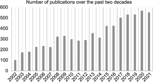
The suspension system, which is conventionally equipped with a coil spring and a hydraulic damper, connects the chassis and the road wheels in a car, ensuring vehicle safety and ride performance [1], [2], [3], [4], [5], [6], [7], [8], [9], [10], [11], [12], [13], [14]. The active suspension systems (ASSs), which additionally introduces an independent force or torque acting between the sprung and unsprung masses, has been a long-term research topic since the 1950s. However, it was not until the 2010s that ASSs begin to be adopted in production cars (especially premium cars) [15], [16]. Their adoption was due to a combination of factors, including: ①the maturation and good commercialization of techniques for electromechanical actuations, micro-controllers, and sensors (e.g., inertial measurement units (IMU)); ② high demand for driving comfort, stability, and safety; and ③ ASSs’ compatibility with the rapid development of vehicle electrification and autonomy. In industry, the automotive suspension market is expected to grow from 4.53 × 10¹⁰ USD in 2022 to 5.16 × 10¹⁰ USD in 2027—a huge demand driven by the rapid increase in global electric vehicle (EV) sales, which rose from 1.3 × 10⁶ units in 2018 to 4.3 × 10⁶ units in 2021. In academia, the overall number of publications on active suspension and control has steadily increased over the past two decades, as shown in Fig. 1.
 Fig. 1. Number of publications on the topic of ASSs over the past two decades (Source: Web of Science).
Most research and review papers on ASSs focus on vehicle dynamics, modeling, and robust control. However, the gap between academic research outcomes and industrial application requirements has not yet been bridged, as car manufacturers demand practical characteristics including a compact structure, small mass increment, low power consumption, high-frequency response, acceptable economic costs, and high reliability. Furthermore, along with the rapid development of vehicle electrification and autonomy, the mechatronic configurations and control strategies of future ASSs may not be designed alone to improve suspension performance but may instead operate cooperatively with other modules in a car (e.g., the steering and braking modules) and high-level decision-making in transportation system (e.g., the driving maneuvers of connected and autonomous vehicles (CAVs)). Ignoring these factors may hinder the transferal of most ASS research knowledge from research to industry. In contrast, this work provides a comprehensive review of ASSs that discusses advances from both industry and academia. In particular, this article discusses state-of-the-art hardware solutions (from the element to system level) developed in the past 5 years in detail, including the representative industrial products of Mercedes active body control (ABC) and Audi predictive active suspension, and novel concepts of variable geometry suspension systems that already show promising potential. It also reports advances in multi-objective ASS control strategies, which aim to ① enhance ride comfort and handling ability, ② improve stability and safety with cooperative assistance from steering and braking mechanisms, ③ improve fuel economy, and ④ better adapt to various driving scenarios by combining with intelligent algorithms. Finally, future research and development directions for ASSs that ① are more compatible with EVs and CAVs and ② pursue higher intelligence are recommended.
The rest of this paper is organized as follows. Section 2 reviews advances in ASS hardware elements, which are categorized according to geometric topology and functions. ASS mechatronic systems that have been adopted in production cars, together with recently proposed novel concepts, are also detailed. Section 3reports ASS control schemes, which have been synthesized to mainly implement ① chassis attitude stabilization in terms of pitch and roll angles, ② chassis vibration attenuation for enhanced ride comfort and road holding, and ③ cooperative operation with other modules in a car to improve driving stability and safety. Section 4 presents other topics in ASS research, including mathematical models, numerical simulations, and experimental validation. In Section 5, we draw key conclusions and recommend future research. The literature survey and research vision provided in this work are intended to guide the development of the next generation of ASSs.
2. State-of-the-art suspension elements and systems
This section categorizes the key hardware elements in ASSs according to geometric topology and functions, before reviewing the state-of-the-art mechatronic systems of ASSs that have been employed in production cars or recently proposed as candidate solutions.
2.1. Hardware elements
An ASS typically contains the hardware elements of ① mechanical arms that connect the chassis and the wheel, ② a spring that compensates for road unevenness and constrains the suspension deflection within a specific range, ③ a damper that dissipates kinematic energy and attenuates chassis vibration, and ④ an active component that is controlled to exert an independent force/torque between the sprung and unsprung masses. Different forms of these elements have been developed and integrated to establish various ASSs, facilitating chassis attitude adjustment, chassis vibration attenuation, vehicle stability improvement, and air drag forces reduction. A categorization of the ASS hardware elements, according to geometry topology and functions, is illustrated in Fig. 2. These elements are further detailed in the following subsections, which may inspire suspension researchers with ideas for new designs of mechatronic system structures.
 Fig. 2. Categorization of the hardware elements in ASSs according to geometric characteristics and functions.
2.1.1. Mechanical connection arms
Generally speaking, three different architecture solutions for mechanical connection arms are adopted in independent suspension design in modern cars; these include the Macpherson strut, the double wishbone, and the multi-link suspension mechanism, whose kinematic layouts are shown in Fig. 3. The Macpherson strut mechanism (Fig. 3(a)) dominates the market due to its low cost, simple structure, easy maintenance, and light weight (on the unsprung mass). However, the Macpherson strut causes a largely varied camber angle (normally, a negative angle at around the strut’s static equilibrium state turns into a positive angle over a large travel distance with suspension deflection) and sideways movement in wheel tires, resulting in less road holding and vehicle stability [6].
 Fig. 3. Kinematic diagrams of three typical arrangements of connection arms in vehicle suspension structures. (a) MacPherson strut, (b) double wishbone, and (c) multi-link suspension mechanisms [12].
The double wishbone suspension mechanism (Fig. 3(b)) provides better stability on the road, because the tires have a larger touching area due to the increased number of linkages and more flexible design (e.g., arm length and joint location) [2]. Multi-link suspension (Fig. 3(c)), which uses three or more lateral arms and one or more longitudinal arms, has begun to be adopted in luxury sports vehicles, due to its excellent ride and handling ability. However, it demands a complex geometrical design (normally aided by multi-body simulation software and three dimensional (3D) design) and has a high price [12], [13].
Concepts for actively controlled connection arms have recently been proposed, in which electromechanical actuations are integrated into one or more joints of the connection arms to adjust the wheel attitude of the camber, toe, and caster, thereby helping the tires to function properly and wear evenly. Representative examples include the variable geometry suspension system and the active wheel alignment system (AWAS), as described later in Section 2.3.
2.1.2. Suspension spring
The suspension spring is a critical component that links the chassis and the wheel at each corner, with the main objectives of compensating for road unevenness, constraining suspension defection stroke, and ensuring a suitable contact force between the road surface and wheel tires. Leaf springs, as shown in Fig. 4(a), are one of the oldest types of suspension springs made up of a cascaded spring set. Their use in passenger cars ended in the 1980s, but they are still popular for use in heavy-duty trucks.
 Fig. 4. Four types of springs used in vehicle suspension systems. (a) Spring leaf; (b) coil springs with constant and variable rates; (c) three types of air springs: the single-acting air spring, double-acting air spring, and double-acting air spring with adjustable piston segment [17]; (d) torsion bar (highlighted in red). The definitions of all the abbreviations in the figure could be find in the cited references.
Cylindrical coil springs with a constant stiffness are mostly used in vehicle suspension systems and come in a few different forms. Nonlinear springs (Fig. 4(b)) appropriately vary the coil shape, with the coil diameter decreasing toward the end of the suspension spring; therefore, they exhibit soft characteristics over a small suspension deflection, while featuring hard stiffness under a significant load transfer [14]. Controllable stiffness springs, commonly referred to as air springs, whose structures are illustrated and categorized in Fig. 4(c), use pressurized air to replace conventional steel springs and have been extensively adopted in coaches and buses. Varying the air pressure makes it possible to adjust the chassis height, leading to significant benefits: ① The “ferry lift,” in which the air suspension is raised above the normal ride height, can assist in loading/unloading the coach on and off ferries, reducing the risk of grounding out over steep ramps, and can also be used on rough ground or steep crests; and ② the “kneel down” ability, as used in public transport buses, helps to reduce the bus’s step height for the easy entrance and exit of passengers. Air springs have been further developed and are utilized in luxury passenger cars to enhance ride comfort, with the spring stiffness (i.e., the air pressure) electronically controlled to adapt to different levels of road irregularities and driving scenarios (as discussed in Section 2.2). The disadvantages of air suspension systems include the air leakage caused by excessive wear and system complexity, as these systems introduce the additional components of air bags, a pneumatic pump, and valves. A torsional bar, as illustrated in Fig. 4(d), is also equipped in the chassis to assist the suspension structure by improving the vehicle’s lateral stability, thus reducing the risk of a rollover.
2.1.3. Suspension damper
The suspension damper is intended to dissipate the kinematic energy and attenuate the vertical vibration of the chassis. Conventional hydraulic dampers dominate the vehicle shock-absorber market, due to their low cost and easy maintenance; however, their damping coefficient is noncontrollable, compromising their overall suspension performance. Recently, a magnetorheological damper [18], which uses an electromagnet to change the viscosity of fluid inside a shocker absorber cylinder, thereby enabling a controllable damping coefficient, has been developed and adopted in some cars to improve ride comfort (e.g., MagneRide, developed by General Motors and first applied in the Cadillac STS in 2002 [15]). Vehicle suspension systems with a magnetorheological damper, also known as semi-active suspension, are discussed later, in Section 2.2. The other drawback of the conventional damper is that the energy is dissipated and lost in the form of heat. According to Ref. [11], the vehicle vibration power dissipated by the suspension damper ranges from 100–400 W for passenger cars and up to 2000 W for buses and coaches. To conserve this energy, different forms of regenerative dampers have been recently developed that enable energy harvesting (and even a controllable damping coefficient). Three representative regenerative dampers are introduced below.
An electrical suspension damper with energy harvesting and a tuneable damping coefficient is proposed and developed in Ref. [19]. As shown in Fig. 5(a), a ball-screw-based mechanism is used to convert translational movement to rotation, driving three generators that are independently controlled by switches. One of these generators connects to a tuneable resistor for the adjustment of the damping coefficient, while the other two regenerate electricity with a constant damping coefficient. By controlling the number of switched-on generators and adjusting the value of the resistor, the suspension damping coefficient can be appropriately controlled to adapt to different driving scenarios and road conditions. In addition to the capability of damping tuning, the multiple controlled generators can output a reasonable amount of electricity of up to 30 W.
 Fig. 5. Different forms of suspension dampers with energy harvesting. (a) Ball-screw-based multiple controlled generators [19]; (b) two-leg mechanism [20]; (c) Audi electromechanical rotary dampers, called eROT [21].
A two-leg motion mechanism has been proposed and integrated in a shocker absorber to enable energy harvesting, as shown in Fig. 5(b) [20]. The damper performance was evaluated under sinusoidal excitation inputs with both amplitudes and frequencies swept, and the experimental results showed that a damping coefficient of up to 1720 N·s·m−1 could be achieved. The mechanical energy conversion efficiency of this two-leg motion mechanism was reported to be between 0.71 and 0.84, which is higher than existing mechanical transmission solutions reported for electrical dampers, such as the ball screw and rack-and-pinion.
Electrical dampers have also begun to be employed in production cars; for example, Audi developed a prototype of an electromechanical rotary damping system, named eROT, which was later installed in the Audi A8 in 2017, showing potential for further applications [21]. The eROT system not only features a controllable damping coefficient and high-efficiency energy harvesting but also enables a highly compact structure. As shown in Fig. 5(c), the horizontally arranged electric motors in the rear axle area replace the conventional shock absorbers, enabling additional space in the luggage compartment. It was reported that the eROT can generate a satisfactory amount of electricity, with an average of 100–150 W reported during testing (from 3 W on a smooth road surface to 613 W over a rough one, corresponding to CO2 emission reductions of up to 3 g·km−1).
2.1.4. Active component
In addition to the hardware elements of the connection arms, spring, and damper, as discussed above, a fully active suspension system introduces an active component that independently exerts a force or torque between the sprung and unsprung masses. A fast response (i.e., a wide-frequency bandwidth) in the force or torque is always pursued in order to implement both chassis attitude stabilization (e.g., chassis leveling) and vehicle vibration attenuation at different frequencies of interests. Regarding the actuation type, electromechanical (e.g., Michelin in-wheel active suspension in 2004 [22] and the Audi Predictive Suspension System in 2017 [23]) and hydraulic actuators (e.g., the hydractive suspension equipped in the Citroën C5 II in 2007 [24]) have been reported, and their strengths and weaknesses in ASS applications are compared in Table S1 in Appendix A. According to the geometric layout, the active component in an ASS can be categorized as series (e.g., series active variable geometry suspension) or parallel (e.g., parallel active link suspension (PALS)), as described in Section 2.3.
2.2. Mechatronic suspension systems in production cars
Individual elements of active suspensions, as reviewed in Section 2.1, are combined and integrated to establish various mechatronic suspension systems for ASSs (and semi-active suspension systems). State-of-the-art mechatronic solutions for ASSs that are adopted in production cars are discussed below.
2.2.1. Cadillac MagneRide Suspension
MagneRide [15] is a typical semi-active suspension solution that was first launched by Cadillac in 2002. Its improved version, MagneRide 4.0 (Fig. 6(a)), was introduced and implemented in Cadillac’s latest models in 2020 and 2021—namely, the CT4-V, CT5-V, and CT5. In MagneRide suspension, the damping rate and tire contact on the road are controlled by magnetorheological fluid within the shock absorber. The latest version of MagneRide 4.0 has the following highlights: ① The updated wheel hub accelerometers and an IMU transmit road disturbances four times faster than its previous version; ② under heavy braking, hard cornering, and other driving conditions, the IMU delivers more accurate readings of body motion relative to the wheel; ③ it delivers more consistent performance by compensating for changes in damper fluid temperature; ④ to improve control of the vehicle body, magnetic flux control is used to provide a more consistent and accurate transition between rebound and compression in the dampers; and ⑤ significant reduction in the damper friction enables a near “no-damping” effect that minimizes the difference between different drive modes.
 Fig. 6. State-of-the-art mechatronic solutions to ASSs adopted by commercial vehicles. (a) Cadillac MagneRide, a typical semi-active suspension system [15], [16]; (b) Michelin In-Wheel Active Suspension [22]; (c) Mercedes-Benz AIRMATIC air suspension [30]; (d) Mercedes-Benz ABC, a type of electrohydraulic suspension [33]; (e) Audi A8 predictive active suspension, which is equipped with a rotary electric actuator (highlighted in red), an air suspension, and a road preview camera [23]; (f) Bose electromagnetic active suspension [37], [38]. AI: artificial intelligence.
Other representative semi-active suspensions include the Öhlins Semi-Active Suspension [25] and the Monroe intelligent suspension, as supplied by Tenneco [26], [27]. Similar to MagneRide, both adjust the damping coefficient of the shock absorber by means of an electrical controlled unit in order to adapt to various road events and improve ride performance. However, in comparison with fully active suspension, semi-active suspension cannot control the chassis attitude in terms of the pitch and roll angles and the chassis height. A comparison between semi-active and active suspension is summarized in Table S2 in the Appendix.
2.2.2. Michelin in-wheel active suspension
Michelin first proposed the active wheel concept in 1996 [22]. Michelin in-wheel active suspension (Fig, 6(b)) has two motors integrated inside a wheel. One is responsible for spinning the wheel and transmitting power to the ground, while the other actuates an active suspension system that helps improve comfort, handling, and overall vehicle stability. The system was developed specifically for electric vehicles (EVs), so it does not require a gearbox, a clutch, a transmission shaft, or an anti-roll bar. All the braking, drive, and suspension components are fitted within a single wheel. Similar to the benefits of an active differential mechanism, the Active Wheel technology exhibits better handling ability than shaft-driven cars. In addition, since there is no need for a conventional engine at the front of the vehicle, this space can be exclusively devoted to impact absorption. However, the effect of shocks, water, and snow on such an “in-wheel” design has not been thoroughly investigated. This project was interrupted in 2014, because the weight increment, space required inside the wheel, and economic costs were unacceptable [28].
2.2.3. Electronic controlled air suspension
Unlike a mechanical spring system that deflects in proportion to the load, the height of air springs can be adjusted independently of the load by adjusting the spring pressure. Electronic controlled air suspension (ECAS), developed by Dunlop Systems and Components Ltd. (Coventry, UK), was first installed in the Range Rover Classic in 1993 and later in the Range Rover P38A [29]. The chassis height is automatically controlled to adapt to driving conditions, while a manual ride-height switch is also offered. ECAS has been widely adopted in high-end grand tourer (GT) cars, such as the Mercedes-Benz AIRMATIC [30] (Fig. 6(c)), Ford Expedition Models [31], Tesla Model S [32], and Audi A8 AI Suspension (Fig. 6(e)) [23].
2.2.4. Mercedes active body control
Mercedes ABC; Fig. 6(d)), is a fully active hydraulic suspension designed by Mercedes-Benz that entered series production in 1999 [33]. The ABC system is capable of independently controlling the spring and damping forces at each wheel to minimize rolling, pitching, and vertical motions. Moreover, the chassis can be actively lifted to increase ground clearance or lowered as required on special occasions. A road surface scan function was later added in the Mercedes-Benz S-Class (W222) in 2013 to enable a predictive control that responds to the road surface 15 m ahead of the vehicle at a driving speed of up to 130 km∙h−1 [34]. Even better ride comfort and handling ability are provided by further combination with the air suspension technique.
2.2.5. Audi predictive active suspension
Audi revealed a high-tech innovation for its flagship model the Audi A8 in 2017 [32]: predictive active suspension, which is a fully active suspension system that consists of a double wishbone, an air spring, a rotary electrical damper, and an electromechanical actuator. These elements and their configuration are shown in Fig. 6(d). The electromechanical actuators raise or lower each wheel independently, actively controlling the chassis height (to a maximum increment of 85 mm) and thereby reducing the air drag force. This offers potential fuel savings of up to 0.7 L per 100 km. In addition, Audi A8 Predictive Active Suspension offers both “dynamic” and “comfort plus” driving modes: In the “dynamic” mode, the Audi A8 only has 2-degree changes in the chassis roll angles for the case of hard cornering at a 1 g lateral acceleration versus more than 5 degrees with a passive suspension. In contrast, the “comfort” mode minimizes the chassis vibration accelerations. In both driving modes, the vehicle rolling moment is optimally distributed to minimize the “diving” feeling during accelerating or braking. The average power consumption of Audi predictive active suspension is 10–200 W, which is significantly less than that of hydraulic suspension solutions.
2.2.6. The ZF “flying carpet” predictive chassis concept
In 2019, ZF developed a new chassis concept named the “flying carpet” [35], [36]—an electrohydraulic active suspension system that is capable of low-frequency chassis attitude control. More importantly, the ZE “flying carpet” connects suspension control with steering and braking systems to deliver a more comfortable ride. This chassis concept also features a road preview control that minimizes the impact of, for example, a speed bump on ride comfort.
2.2.7. Bose electromagnetic active suspension
It has been decades since Bose first demonstrated an electromagnetic suspension system that perfectly leveled the vehicle chassis, irrespective of road bumps, at a low driving speed. Recently, Bose designed a novel tubular permanent magnet electromagnetic actuator (Fig. 6(f)) to replace the conventional spring-damper unit at each corner of the chassis [22]. The actuator features ① a direct drive with a small occupied volume; ② a higher frequency bandwidth, as compared with other fully active systems; and ③ a lower power consumption than that of an electrohydraulic system in which continuous hydraulic pressurization is needed.
2.3. Novel concepts
2.3.1. The variable geometry suspension system
The variable geometry suspension system is a novel solution for improving road holding [39], [40], [41], [42]. The control manipulator of the system is the camber angle of each wheel, as driven by a hydraulic cylinder (Fig. 7(a)). Changes in the wheel camber angles will influence the yaw rate of the vehicle, thus reducing the tracking error relative to a reference yaw rate. Furthermore, the height of the roll center and the half-track can be actively modified by controlling the camber angle of each wheel, enabling improved vehicle ride performance such as trajectory tracking and lateral stability.
 Fig. 7. Various concepts of variable geometry suspension systems. (a) A hydraulic cylinder-driven variable geometry suspension system, which actively controls the upper arm joint and thus the camber angle of the road wheel [42]; (b) two link-based mechatronic suspensions—series active variable geometry suspension (SAVGS; proposed in Refs. [43], [44], where the torque is provided by a rotary motor and acts on the single link F–G), which actively controls the orientation and the compression/extension of the spring damper and thus the vertical tire force, and parallel active link suspension (PALS; proposed in Ref. [49]), which actively controls the torque applied to the rocker-push rod assembly K–J–L; (c) illustration of three wheel alignments adjusted by the AWAS, where the camber, toe, and caster are shown from left to right [55], [56]. The definitions of all the abbreviations in the figure could be find in the cited references.
2.3.2. Series active variable geometry suspension
Series active variable geometry suspension (SAVGS) has been conceptualized in Refs. [43], [44], [45], [46], [47], [48] and is believed to be especially suitable in a GT car, which has stiff suspension springs and a light vehicle chassis. Fig. 7(b) shows the schematic of SAVGS application to a double-wishbone suspension, where an active component of the single link (F–G) is introduced between the spring damper (E–F) and chassis. The rotation of the single link with respect to the pivot joint, “G,” operates within the range of [0, 180]°, where is defined as ( is the single link angle at the static equilibrium state). Therefore, if the road wheel is assumed to be fixed, = 0°(corresponding to the static equilibrium position) leads to a lowest chassis height, while = 180°means that the chassis is lifted up by the maximum amount. Moreover, both the variation of the spring-damper force and the vertical tire force are most sensitive to the rotation of the single link at around the nominal equilibrium state (= 90°). The main features of SAVGS include:
-
•
Low-frequency chassis attitude control; for example, SAVGS is capable of fully eliminating the roll angle variation of the chassis when the lateral acceleration () is up to 3.5 m∙s−2 for a sports utility vehicle (SUV) and up to 5.5 m∙s−2 for a GT.
-
•
High-frequency chassis vibration attenuation in terms of the rolling, pitching, and vertical acceleration, which improves ride comfort and handling ability over high-irregularity road surfaces.
-
•
Small inertia of the introduced active component (i.e., the single link), where benefits of negligible increment to the unsprung mass, and high frequency response in the link motion are expected.
-
•
A fail safe, since the SAVGS system can switch back to the original passive suspension if the single-link actuator suffers power loss or even failure.
2.3.3. Parallel active link suspension
Another link-driven mechatronic suspension, PALS, has been conceptually proposed and physically implemented in a quarter-car demonstration rig [49], [50], [51], where the initial testing results show promising potential. As shown in Fig. 7(b)), a rocker-pushrod assembly (K–J–F) is introduced in parallel with the spring damper. The active element of the rocker (K–J) is driven by a rotary actuator to deliver a torque acting from the chassis onto the lower wishbone, enabling the possibility of improving the suspension performance. Compared with passive suspensions, PALS features both chassis attitude stabilization and ride comfort and road holding improvement at their frequencies of interest. PALS has features similar to those of SAVGS, but it is considered to be more suitable for heavy cars with soft suspension springs, such as SUVs [52], [53], [54].
2.3.4. The DOFTEK AWAS
The DOFTEK AWAS has been in development for two years, with the aim of enabling cars to adjust the three alignment orientations: the camber, toe, and caster (see its configuration in Fig. 7(c)) [55]. The AWAS can be installed on any type of suspension design, including MacPherson struts, double wishbone suspensions, multi-link suspensions, rear-wheel-steered vehicles, commercial trucks, and trailer wheels. It can minimize rolling resistance to save fuel, increase the range of an EV, reduce tire wear in general, and decrease tire temperatures. The AWAS consists of two electromechanical devices, one installed on the original equipment manufacturer (OEM) suspension mount for caster and camber adjustments and the other placed on the tie rod for toe adjustments. Both adjustments are controlled by a DOFTEK control unit. The weight increment introduced by the AWAS to the overall vehicle is approximately 4 kg. The AWAS was first implemented in the Audi TTRS and Mercedes-AMG GT S.
2.4. Cost, weight, and space requirements
Different categories of cars are likely to have different requirements for ASSs in terms of costs, weight, and space. For example, high-end luxury cars can accept a higher economic cost, while SUVs can tolerate more weight increment from the ASS than GT cars. Existing numbers reflecting the ASS cost and weight increment are summarized below.
In terms of the weight increment of the ASS in a full-sized car, Bose representatives have explained what is needed to bring the suspension to market in a production car by the end of the decade: The cost would have to come down to a reasonable level for a high-end car, and the weight would have to come down to no more than 50 lbs (22.7 kg) per corner more than the existing suspension. Thus, a production car would weigh an extra 200 lbs (90.7 kg) [37]. It has also been reported that an estimated 37.7 kg weight increment is introduced by a recently developed prototype of SAVGS based on a Mazda MX5 [51], and only a 4 kg weight increment is introduced by the novel AWAS developed by DOFTEK [55].
In terms of economic cost, it has been reported that Porsche’s active suspension management system is priced according to the model on which it is specced: around 1000 GBP on the 718 Boxster and Cayman, and a similar cost on the Cayenne, but around 800 GBP on the Macan. The system on the Porsche’s two SUVs can also be specced as a package with air suspension for around 1900 GBP on the Macan and 2600 GBP on the Cayenne [57]. The Audi A8 offers its optional Predictive Active Suspension for around 5450 EUR (4700 GBP) in Europe. A full-car experimental prototype of SAVGS cost 8827 GBP with off-the-shelf components, although this is expected to be substantially reduced in application to production cars [51].
In terms of space occupation, EVs offer more space than fuel cars for deploying ASSs, due to the absence of the internal combustion engine in the front axle.
2.5. Summary of active suspension hardware structures
Modern ASSs not only introduce an element that actively exerts forces and torques between the sprung and unsprung masses but also contain advances in each hardware element: from the conventional Macpherson/double wishbone structures to multi-link connection arms; from the conventional coil spring to the air spring, the pressure of which can be actively electronically adjusted to enable controllable spring stiffness; and from the conventional hydraulic damper to the electrical rotary damper, where both tunable damping and energy harvesting can be achieved.
In addition to suspension performance improvement, the features of small weight increment, realistic occupied space, high-frequency response, low economic costs, and low energy consumption are always pursued in mechatronic structures of ASSs, making the ASSs more practically feasible and thus more likely to adopted by car manufacturers [58], [59], [60], [61], [62], [63], [64], [65], [66], [67], [68], [69], [70], [71], [72]. Among these state-of-the-art ASS solutions, Audi predictive active suspension and Mercedes ABC are the two representative examples. In academia, the two link-based mechatronic suspensions of SAVGS and PALS have been recently proposed and experimentally validated, showing promising potential with low inertia, fast response, negligible unsprung mass increment, and fail-safe characteristics.
3. Control strategies
The general control objectives and requirements of ASSs are categorized and stated in this section. These include: chassis attitude stabilization at lower frequencies to achieve desirable vehicle dynamics, such as zeroing the roll angle at cornering, lifting the chassis for road clearance, adjusting the pitch angle for reduced air drag forces, and so on; vehicle vibration attenuation at higher frequencies that can be sensed with human perception (e.g., 4–8 Hz for chassis vertical acceleration and 1–2 Hz for rolling and pitching accelerations); and penalization of the control effort at higher frequencies (> 15 Hz) to reduce unnecessary energy consumption by the ASS actuation (outside the frequencies of interests).
In addition to the essential control objectives mentioned above, more “intelligent” ASS control strategies are pursued that simultaneously enable multiple functions and switch the control focus to adapt to different driving situations. For example, an ASS may focus on reducing air drag forces and conserving energy in applications such as connected and autonomous transportation systems and racing cars, or it may focus on improving ride comfort and road holding for family driving journeys over a rough road surface.
Moreover, ASS control robustness must be considered and ensured in order to deal with vehicle uncertainties, such as ① the variable payload, as affected by the number of passengers; ② the variable damping coefficients, as determined by the suspension compression/extension rate; and ③ the dynamics of the actuator output in the ASS, as influenced by the load.
3.1. Chassis attitude stabilization
For chassis attitude stabilization, the proportional integrative derivative (PID) algorithm remains the most-used control algorithm, although it has been further combined with intelligent algorithms (fuzzy logic, neural networks, etc.) to adjust control tuning parameters that better deal with varied road conditions [73]. Nonlinear control algorithms for sliding mode control and backstepping control have also been reported to stabilize chassis height.
3.1.1. Proportional integrative derivative control
Although numerous advanced control algorithms have been proposed for motion tracking, PID control is still mostly adopted in industry, as it is simple yet effective and does not require models [74]. For ASS applications, a multi-objective PID control scheme was proposed for a recently suggested link-based mechatronic suspension of SAVGS to enable different forms of chassis attitude stabilization, including ① the heave motion, ② the roll angle, ③ the pitch angle, and ④ the overturning couple distribution (OCD; between the front and rear axles) [45]. The general configuration is shown in Fig. 8. At the front-left corner of the chassis (i = 1), C11, C21, …, CN1 are a group of PID controllers that respectively deal with the four objectives listed above, among others. The PID gains in C11–CN1 are tuned and updated by a higher logic controller, which adapts to different driving situations and aims to improve the vehicle dynamics. In the figure, s11, s21, …, sN1 are measurement feedback for the PID controllers. The control outputs – form an overall angular reference position of the single link in the SAVGS system at the front-left corner, with the angular limits respected. Overall, the single link at each corner is coordinated to adjust the chassis attitude. This multi-objective PID control scheme can be generalized for adoption by other ASSs.
 Fig. 8. A general multi-objective PID control scheme for chassis attitude stabilization [45]. This example is shown with a recently proposed link-based mechatronic suspension of SVAGS [43], [44], where is the actively controlled angular position of the single link in the SAVGS. The definitions of all the abbreviations in the figure could be find in the cited references.
3.1.2. Sliding mode control
Sliding mode control is intended to help develop a variable structure controller, which drives the system to move into the neighborhood of a designed sliding surface and then constrains the system to slide along this surface. In Refs. [75], [76], a nonlinear controller based on sliding mode control is designed for an air suspension system to adjust the height of the vehicle sprung mass (height control) and to regulate the roll and pitch angles of the vehicle body (leveling control). The tracking accuracy and robustness are improved by overcoming nonlinearities and uncertainties in the suspension systems. Moreover, a sliding mode observer is designed to estimate the pressure inside four air springs.
3.1.3. Backstepping control
The backstepping control method is a recursive design procedure that links the choice of a control Lyapunov function with the design of a feedback controller and ensures the global asymptotic stability of strict feedback systems. An adaptive backstepping control strategy for ASSs to stabilize the chassis attitude in the presence of parameter uncertainties has been proposed in Ref. [77], with the suspension deflection, the vertical tire force increment, and actuator saturations considered as “hard constraints” and ensured within their allowable ranges.
3.2. Chassis vibration attenuation
Aside from chassis attitude stabilization, as discussed in Section 3.1, chassis vibration attenuation is another significant feature of ASSs that enhances the ride comfort and road holding performance. A group of control strategies have been developed to minimize the propagation from road-unevenness disturbance to chassis vibration; they include Skyhook control (for semi-ASSs), the linear quadratic regulator (LQR) and linear quadratic Gaussian (LQG), H-infinity (H∞)/H2 control, μ-synthesis control, sliding mode control, backstepping control, and so on. Recently, these classical methodologies have been further combined with intelligent control, such as fuzzy logic [78], [79], [80], [81], [82], [83], [84], [85], [86], [87], [88], [89], [90], neural networks [91], genetic algorithms, and the emerging techniques of data-driven control systems [92], enabling adaptive control that better deals with varied road conditions and driving scenarios.
3.2.1. Skyhook control
Skyhook control has been widely adopted by semi-ASSs to improve ride comfort. In this strategy, the controlled force-producing elements emulate a damper that connects the chassis and the inertial reference (or virtual sky) [93], [94]. This damper restricts the motion of the sprung mass, thus reducing vibrations caused by external disturbances. Skyhook control is a basic method for control design with semi-active suspension. However, it does not consider the unsprung mass vibration, which directly influences the road holding quality.
Ground-hook control was subsequently proposed, in which a virtual damper is added between the ground and the unsprung mass [95]. This strategy aims to reduce variation in the vertical tire force and thus enhance the road holding ability; it is especially suited to heavy vehicles. Skyhook and ground-hook control can be combined to improve both the ride comfort and the road holding with respect to passive suspension. Moreover, Skyhook control was recently further developed to integrate the concept of adaptive control, with the damping manipulation variable being adjustable so it can be tuned to be an appropriate value to adapt to the road situation [96], [97], [95].
3.2.2. LQG and LQR
Both LQR and LQG are used to address optimal control problems, where the objective is to find a controller that minimizes a quadratic cost function subject to the linear system dynamics. When LQR and LQG frameworks are applied to a linear quarter-car or half-car model with ASSs, the suspension performance objectives of the ride comfort and road holding, as well as the energy costs of the control manipulation variables, are expressed through a quadratic index [98], [99]. Appropriate matrices are added and tuned to weigh the importance of different objective variables. However, both LQR and LQG perform active suspension optimal control based on hand-derived linear models, which ignore the nonlinearities and uncertainties of vehicle systems; therefore, the real vehicle applications do not exhibit as promising a performance enhancement as the linear analysis indicates.
Optimal control techniques can well fit ASSs, which is intended to minimize the gains from the disturbances of road unevenness and the load transfer to improve the objective variables related to chassis vibration. LQG and LQRs are representative optimal control techniques that are particularly suited to linear quarter-car models with ASSs.
3.2.3. H∞/H2 control
The H∞ methodology has been widely applied to linear multiple-input and multiple-output (MIMO) systems, due to its robustness [100]. This control technique aims to minimize the propagation from exogenous disturbances to system performance objectives. Mathematically, the H∞ control aims to find an optimal controller that minimizes the linear fractional transformation according to the definition of the H∞ norm:(1)
where is the system plant, is the maximum singular value of the matrix , and “” refers to the least upper bound. H2 control instead minimizes the H2 norm of MIMO systems, which is defined as follows:(2)
H∞ control has been extensively employed in ASSs to enhance ride comfort and road holding by minimizing the disturbance from road unevenness on the performance objectives, such as vertical chassis acceleration, vertical tire force increment, and so on [48], [49], [50], [51], [101], [102].
3.2.4. μ synthesis control
The μ synthesis technique extends the methods of H∞ synthesis to design a robust controller for a system plant with structured uncertainties. In ASSs, the main uncertainties include ① the variable payload, as affected by the number of passengers; ② the variable damping coefficients, as determined by the suspension compression/extension rate; and ③ the dynamics of the actuator output in the ASS, as influenced by the actuation load [53]. By setting the ranges of these uncertainties, μ synthesis can be performed by following the similar control frame of the H∞ methodology.
3.2.5. Model predictive control
Another robust control algorithm that is widely employed in ASSs is model predictive control (MPC), in which parameter uncertainties can be tolerated through iterative computing and optimization to ensure system robustness [103], [104]. Linear or nonlinear models of the system dynamics can also be updated iteratively and thus precisely constructed [103]. Further aided by road preview technology (enabled by a camera), MPC can take the variation of the road profile ahead as a known input disturbance, facilitating a powerful solution for ASS control, as MPC can compute an optimal sequence of control manipulation variables over the control horizon [105].