1. Introduction
The escalating heat generated by a wide range of electronic devices and components has created an urgent need for advanced cooling technology that can ensure optimal performance and improved reliability. To avoid system failure due to overheating, it is essential to utilize an efficient and innovative cooling method to keep the processor temperature within safe limits. Straight rectangular fins heat sinks are commonly used in various industries due to their simple manufacturing process and effective heat transfer management, including engines, turbine blades, and automotive vehicle heat exchangers [1]. The primary function of a heat sink is to dissipate excess heat away from the processor, keeping its temperature within the recommended limit of 100 °C [2]. In recent years, micro and mini-channel heat sinks have been extensively studied, and detailed reviews can be found in Refs. [3,4]. Parallel channels are used to make the heat sinks, which provide a greater surface area for contact between the heat sink and cooling fluid. According to Kandlikar and Grande's classification [5], microchannel heat sinks have channel hydraulic diametersranging from 10 μm to 200 μm, and the hydraulic diameter of the channels in mini-channel heat sinks is typically between 200 μm and 3 mm [6]. The effectiveness of microchannel heat sinks for dissipating heat is noteworthy [7]. The requirement for increased pumping power is a limiting factor for the application of microchannels in condensed heat dissipation mechanisms. [8], The smaller hydraulic diameters are a factor that can be linked to this occurrence [9]. On the other hand, mini-channel heat sinks present a feasible substitution to microchannel heat sinks in compact heat elimination systems owing to their lesser pressure prerequisites, despite their thermal output remains limited. The problem can be adequately resolved by employing a range of techniques designed to improve the transfer of heat. Additionally, the flow maldistribution occurring in the micro/mini-channels of a heat sink is predominantly attributed to the suboptimal design of the distributor and collector headers, which are intended to assist the inlet and outlet of the coolant and are positioned on either side of the channels. Numerous investigations have concentrated solely on ameliorating the thermohydraulic effectiveness of heat dissipation devices through the utilization of modifying the thermophysical characteristics of the coolant with nanofluids [10], creating cavities on the walls of the channels [11], tapered ducts [12], circular [13], and implementing magnetic fields [14]. A sequence of numerical explorations on corrugated channels with distinct types of nanofluids was conducted by Ajeel et al. [[15], [16], [17], [18], [19], [20]]. The corrugation profile effects resulted in an increase in the average Nusselt number compared to smooth channels, also was got a reduction in pressure was achieved. In another study [[21], [22], [23]] the study examined the influence of geometrical factors on thermal-hydraulic performance (PEC) in different corrugated channels. The simulation outcomes revealed that the height-to-width ratio was more impactful than the pitch-to-length ratio concerning PEC. The alteration of flow structures can be observed upon the increase of Reynolds number and nanoparticle volume fraction.
The following is a concise of techniques for improving thermal performance in multi-micro/mini-channel heat sinks.
The interruption of the microchannel and adding staggered ribs is a beneficial technique for enhancing the redeveloping thermal boundary layer by combining streamwise-periodic variations of cross-sectional area and microchannel, as demonstrated by Chai et al. [[24], [25], [26], [27], [28]]. Mitra et al. [29] conducted a comprehensive design analysis of mini-channel heat sinks to determine their optimal dimensions. The heat transfer characteristics of a rectangular mini-channel heat sink with fins on a substrate subjected to consistent heat flux at the bottom were investigated through numerical simulation. The modified boundary condition established at the base of the fins was considered appropriate, given the high sensitivity of the heat flux distribution from the substrate bottom to the convective fluid with a small hydraulic diameter in the flow channels. The accuracy of the boundary condition was verified against a fully conjugate CFD simulation before it was applied to find a solution for the governing equation of fin heat transfer, The results obtained from the analytical solution showed a high degree of agreement, with an error margin of only 2%, and were further compared to experimental data which also revealed good agreement. The study was conducted to investigate the impact of varying channel dimensions on thermal resistance, and it was recommended that geometric fin efficiency be used as a means of determining the optimal channel depth or fin height. Tang et al. [30] simulated numerically to investigate the flow distribution in a Self-Similarity Heat Sink (SSHS) and the effect of overflow channel geometry. The outcomes demonstrated a significant flow maldistribution within the SSHS, which necessitated modifications to the inlet plenum and inlet manifold channel with a tapered contracting structure to solve the problem and enhance overall performance. These modifications reduced the maximum temperature on the cover plate by around 24 K for a heated area of 10 × 10 with a uniform heat flux of 1.5 MW .Kumar et al. [31] propose a modified novel entrance/exit arrangement with various flow entrance angles (θ = 120°, θ = 105°, and θ = 90°) to increase the cooling capacity of mini-channel heat sinks by achieving uniform flow distribution through all parallel mini-channels. The proposed mini-channel heat sink is numerically analyzed using ANSYS-Fluent, with water as the working fluid and aluminum as the heat sink material. The study considers a total of 28 parallel mini-channels with the alteration in flow entrance angle causing a modification in flow distribution where the hydraulic diameter is 1.5 mm. The proposed entrance/exit arrangement with θ = 105° results in the minimum flow maldistribution, leading to better and uniform cooling of the heat sink. In their research, Xia et al. [32] investigated the influence of inlet/outlet locations and header shapes on microchannel fluid flow and heat transfer, revealing that the I-type entrance/exit location provided the best flow distribution and a rectangular header shape achieved uniform flow distribution. Hithaish et al. [33] conducted a numerical investigation of the fluid and heat transfer characteristics of a triangular micro pin fin heat sink (TMPFHS) with different geometrical configurations. A 3D numerical simulation was performed for a triangular finned heat sink arranged in a staggered manner under a thermal energy flux of 10 W . A single-phase laminar flow of coolant water was considered for Reynolds numbers ranging from 100 to 900. The results showed that the heat dissipation rate for all configurations increased significantly with the increase in pressure drop. To determine the most efficient heat sink in terms of maximum dissipation and minimum pressure drop, a non-dimensional parameter, the thermal performance index (TPI), was utilized. The configuration with an alternate forward and backward arrangement demonstrated superior performance with a TPI ranging from 1.01 to 1.44, outperforming all other configurations. Fatimah et al. [34] The study scrutinized the hydro-thermal performance configurations of multi-mini-channels heat sinks (MMCHS) through numerical simulations. The study analyzed the effect of selected inlet/outlet locations and three channel configurations of the cooling water on the flow distribution between channels. The results revealed that the new modified channels can improve heat transfer compared to conventional straight channels, with the wave-shaped channels exhibiting the highest enhancement in Nusselt number. Pistoresi et al. [35] explored the optimization of distributor/collector pipe shapes to attain a uniform flow distribution in an array of parallel mini-channels. The authors introduced and examined a Z-type ladder fluid network featuring 10 parallel mini-channels with a square cross-section. To optimize the shape of distributor/collector pipes, the study employed two methods: an optimized discrete stairway shape and a continuous tapered shape with an inclined angle ranging from 0 to 30. The ANSYS FLUENT code was used to perform 3D-CFD simulations. The numerical results indicated that the discrete stairway shape or continuous tapered shape distributor/collector can achieve a relatively uniform flow distribution at very low flow rates. For higher flow rates, a more uniform flow distribution can be obtained by using larger inclined angles or fewer parallel channels. Aliabadi et al. [36] The study investigated the effectiveness of innovative mini-channels with wavy structures improving the temperature uniformity of heat sinks and decreasing the junction temperature. Both numerical simulations and experimental validation were used, revealing that the proposed mini-channels resulted in a significant improvement in thermal performance, with a maximum decrease of 11.5 K and a 2.35 times reduction in total thermal resistance. Despite a trade-off between reducing thermal resistance and pressure drop, the novel mini-channels demonstrated superior performance index values, particularly at higher Reynolds numbers. Mu et al. [37] conducted a numerical study to investigate temperature uniformity in a water-cooled mini-channel heat sink operating at high heating fluxes. The findings indicate that a heat sink with variable-height channels and circular turning distributor can decrease temperature non-uniformity to below 1 K even with a 2 MW thermal energy flux.
Previous studies have focused on improving the thermal efficiency of MMCHS by tackling the issue of flow maldistribution through the amelioration of flow distribution. Researchers have approached this subject matter through the implementation of two methodologies: The first method looked at the impact of relocating the entrance and exit for cooling fluid through MMCHS while leaving the conventional straight channel form unchanged or changing channel shape, while the second method used grooves in passages or adding ribs, etc. This study will center its attention on the examination of the rebuilding of MMCHS through the utilization of altered channel arrangements, reducing the misdistribution of coolant fluid. The hydrothermal performance of MMCHS is assessed through the numerical evaluation of novel three channel configurations, which are based on the conventional straight design. These configurations include square fin, rectangle with square pin fins, and square fins with square pin fins.
2. Description of the problem
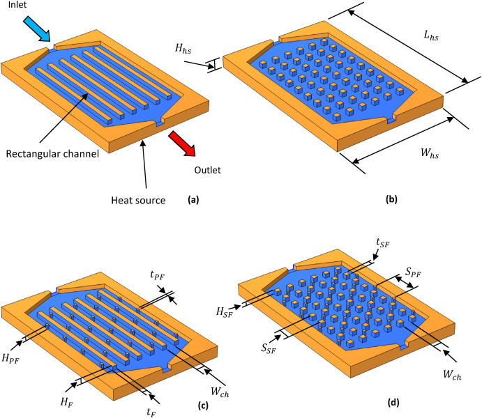
The MMCHS is a commonly utilized method in engineering to dissipate heat from electronic parts due to its small pressure drop compared to other mini-channel heat sinks (MCHS). The conventional multi-mini-channel heat sink (CMMCHS) shown in Fig. 1a displays seven linear channels where the cooling water travels to collect heat from the solid object, while the heat source is situated beneath the heat sink to ensure even heat distribution. However, the essential point in CMMCHS is the uneven distribution of the coolant, with the greatest part entering the middle channel and very little entering the side passages. To improve performance using passive heat transfer techniques, three designs are proposed to remix the flow of the cooling water inside the passages. The first design (shown in Fig. 1b) adds square fins to increase the thermal transmission between the copper and the coolant liquid while maintaining the same surface area for heat transfer. This design called the square fin multi-mini-channel (SMMCHS) heat sink, slightly refines the distribution of the coolant by causing it to flow around the square fins. The second design (shown in Fig. 1c) adds square pin fins while keeping the rectangular channels, resulting in the square pin multi-mini-channel heat sink (SPMMCHS). This design reduces the maldistribution of the cooling fluid by causing it to flow around the square pin fins. Finally, the third design (shown in Fig. 1d) combines both square fins and square pin fins, resulting in the square and square pin multi-mini-channel heat sink (SSPMMCHS). This design refines the blending of the coolant, leading to better thermal transmission between the solid and the coolant.
 Fig. 1. Diagrams of multi-mini-channel cooling systems with various designs: (a) CMMCHS, (b) SMMCHS, (c) SPMMCHS, (d) SSPMMCHS.
3. Numerical and physical specifics
3.1. Representation of the physical model
The multi-channel cooling systems physical models, depicted in Fig. 1, have dimensions of a height () of 5 mm, 50 mm width (), and 75 mm length (), and contain seven passages that have rectangular shapes with 4 mm (), a 2 mm passages fin height () of, and a 2 mm fin thickness () for rectangular passages. For the square fin channels, the square fin thickness () is 2 mm and the space between the centers of two square fins () is 4 mm, with a fin height () of 2 mm. Meanwhile, for the rectangular channels with square pin fins, the pin fin thickness () is 1 mm, the space between the centers of two square pin fins () is 12 mm, and the pin fin height () is 2 mm. Four different channel shapes are analyzed as water with a temperature of 298 K flows through them, rejecting heat from copper and increasing the temperature of the water, with the entrance velocity determined by the Reynolds number for laminar flow and the upper surfaces of the MMCHSs insulated while the bottom surfaces are exposed to uniform heat flux, namely rectangular (CMMCHS), square fins (SMMCHS), rectangular with square pin fins (SPMMCHS), and square fins with square pin fins (SSPMMCHS). Performance evaluations are conducted on all MMCHS models with identical design parameters and operating conditions.
3.2. Representation of the numerical model
A pair of computational domains make up the MMCHS, designed to simulate thermal transmission through copper conduction and coolant convective heat transfer. The thermal recipient base, encompassing walls, and numerous perpendicular axis fins compose the solid domain. The domain of fluid pertains to the movement of fluid within the MMCHS passages. To complete the simulation process, the behavior of MMCHS within solid and fluid domains can be done by setting boundary conditions. It is important to carefully specify the boundary requirements and follow the rules of physics to obtain accurate solutions for fluid flow and thermal transmission problems. There are two categories of boundary conditions: hydraulic and thermal. The boundary conditions and computational domain employed in the SSPMMCHS are represented in a simplified manner in Fig. 2a., while Table 1 provides the hydraulic and thermal boundary conditions for all cases considered. The specific heat, density, and thermal conductivity of the copper used in the simulation are 385 (J ), 8933 (kg ), 401 (W ), respectively. Also, the specific heat is 4182 (J ), density is 997.2 (kg ), and thermal conductivity is 0.6 (W ) for the water used in the simulation.
 Fig. 2. (a) The boundary conditions used in its computational domain of SSPMMCHS (b) a close-up of the mesh distribution for its solid and fluid components.
Table 1. Hydraulic and thermal boundary conditions.
| Hydraulic boundary condition | Thermal boundary condition | |||||||||||||||||||||||||||||||||||||||||||||||||||||||||||||||||||||||||||||||||||||||||||||||
|---|---|---|---|---|---|---|---|---|---|---|---|---|---|---|---|---|---|---|---|---|---|---|---|---|---|---|---|---|---|---|---|---|---|---|---|---|---|---|---|---|---|---|---|---|---|---|---|---|---|---|---|---|---|---|---|---|---|---|---|---|---|---|---|---|---|---|---|---|---|---|---|---|---|---|---|---|---|---|---|---|---|---|---|---|---|---|---|---|---|---|---|---|---|---|---|---|
| Inlet | CMMCHS | SMMCHS | SPMMCHS | SSPMMCHS | CMMCHS | SMMCHS | SPMMCHS | SSPMMCHS | ||||||||||||||||||||||||||||||||||||||||||||||||||||||||||||||||||||||||||||||||||||||||
| = (0.2637–0.5653 m ), , | ||||||||||||||||||||||||||||||||||||||||||||||||||||||||||||||||||||||||||||||||||||||||||||||||
| Outlet | ||||||||||||||||||||||||||||||||||||||||||||||||||||||||||||||||||||||||||||||||||||||||||||||||
| Bottom surfaces | ||||||||||||||||||||||||||||||||||||||||||||||||||||||||||||||||||||||||||||||||||||||||||||||||
| Upper surfaces | ||||||||||||||||||||||||||||||||||||||||||||||||||||||||||||||||||||||||||||||||||||||||||||||||
| Interface surfaces of solid and fluid | ||||||||||||||||||||||||||||||||||||||||||||||||||||||||||||||||||||||||||||||||||||||||||||||||
| Other surfaces |
The numerical method known as the finite element technique is utilized to solve partial differential equations (PDEs). In the realm of simulations of laminar flow, the governing equations for fluid motion are referred to as Navier-Stokes equations. In the COMSOL software, the fluid flow issue's domain is fragmented into a grid of finite elements, which interconnect to form a meshnetwork. The finite element method estimates the solution of the governing equations within each element by representing the field variables, namely, velocity and pressure. The mesh that constitutes the computational domain is composed of interconnected finite elements. The type of element selected for the mesh (Tetrahedra, Pyramids, and Prisms) was determined by the problem's geometry and dimensionality in the present study. Table 2 shows the types, size, and number of grids used in the SSPMMCHS design. Table 2. Specifications of mesh.
Boundary conditions, such as velocity inlets, pressure outlets, and solid walls, are applied to the appropriate boundaries of the computational domain. These conditions specify the behavior of the flow at the boundaries and are incorporated into the system of equations. The hydraulic boundary conditions were carefully controlled during the study. Zero velocity was maintained at most boundaries, except for the passage entranceway and exit. Within the spanning of 0.2637–0.5653 m , the entrance velocity. At the outlet of the channel, a boundary condition was established to regulate the pressure, whereby a pressure gauge of 0 Pa was implemented to define the area of the outlet under ambient conditions. The MMCHS pressure difference was assessed by calculating the discrepancy between the entrance and exit pressures. The “no-slip” boundary condition was utilized in resolving the momentum equations at the surface. The thermal boundary conditions employed water as the coolant. The COMSOL software was utilized to select standard values for thermal conductivity, viscosity, specific heat, and density. At the inlet of the channel, a consistent temperature of 298 K was upheld for the cooling water. The solid surface conditions acted as an intermediary between the fluid and solid components for the fins, covers, and walls. Adiabatic boundary conditions were implemented on the majority of the solid boundaries, except for the base wall of the MMCHS, while a constant heat flux was maintained at the lower wall. The analysis made several assumptions, including a single-phase, laminar, and steady fluid flow with convection heat transfer and negligible radiation heat transfer. Additionally, the MMCHS material was assumed isotropic and homogeneous, with uniform heat flux on the bottom surface and adiabatic outer surfaces. From these assumptions, the governing equations for the flow through the MMCHS were determined [[38], [39], [40], [41], [42], [43]]. -Continuity equation(1) -Momentum equation(2)(3)(4) -Energy equation for the cooling fluid(5) -Energy equation for the solid(6)In the equations governing the flow through the MMCHS, several variables were used. These included P, which represents the pressure at a particular location in the coolant, and the temperature, denoted by T, which was accompanied by the coolant density represented by , while νcw represented the cooling water kinematic viscosity. , represented the specific heat of water, and , represented the thermal conductivity of the cooling water. Finally, was used to denote the solid thermal conductivity. It is essential to conduct a mesh independence test to determine the optimal number of elements required for achieving the highest accuracy in a simulation study while minimizing the cell number. A selection of element numbers is determined according to the models' size., Once the mesh has been increased to a certain number, the results of the substantially are no longer affected. Further mesh refinement becomes unnecessary and only increases the solver's run time. For this study, five various cell numbers were selected, spanning 710,000 to 6,100,000, and tested at a thermal energy flux of 20 kW and mass flow rate of 0.0045 kg . The selected number of elements are listed in Table 3, which illustrates the impact of the element count on both the pressure drop and the Nusselt number in MMCHSs. The complexity of the MMCHS shape determines the number of counts required to achieve stable results in the simulation. More complicated shapes necessitate a greater number of elements, as shown in Table 3 and Fig. 2b. Table 3. Mesh independence.
4. Data analysisThe thermal and hydraulic performance of the MMCHS can be evaluated using parameters such as the Nusselt number and pressure drop. To calculate the heat gained by the water passing across the MMCHS, the following equation is used:(7) and are used to represent the temperatures of the cooling water at the entrance and exit of the MMCHS. Using Newton's law of cooling, the average heat transfer coefficient () may be computed as follows [44]:(8)where, Q, represents the heat gain supplied to the MMCHS, , represents the effective heat transfer area per MMCHS, while represents the average wall temperature of the MMCHSs, and , which represents the bulk cooling water temperature. The process for determining the temperature of the bulk cooling water is expressed as follows [34]:(9) The Nusselt number is commonly utilized for evaluating the thermal efficiency of multi-micro/mini-channel heat sinks by computing the average value, and is calculated as [45]:(10)where Dh and λcw are the passage's hydraulic diameter and the thermal conductivity of the cooling water, respectively. The hydraulic diameter of the channel is defined by the following expression [46]:(11)where Wch and Hch are the channel width and height, respectively. The calculation for the pressure drops across the MMCHS is as follows:(12) The thermal performance of a heat sink is usually reported in terms of the average thermal resistance, along with the Nusselt number, pressure drops, and other performance evaluation criteria. These values can be defined and calculated using the following equations [47]:(13)where is the average temperature of the heat sink base (K), is the entrance temperature of water (K) and Q is thermal energy at the bottom of the heat sink (W). Passive techniques for enhancing heat transfer often result in an increase in ΔP(Pa). To assess the effectiveness of these methods, a performance index (η) is commonly employed as a standard. The performance index provides a measure of the enhancement in thermal transmission resulting from a new design in comparison to the traditional design, relative to the increase in ΔP(Pa). A successful design is indicated by a performance index greater than one, which mathematically expresses that the improvement in heat transfer exceeds the increase in pressure drop [48,49].(14)where Nu ref and ΔP ref are used to represent the average Nusselt number and pressure drop of the CMCHS. 5. Results and discussionTo validate the numerical simulation outcomes, the pressure drops ΔP(Pa) and average Nusselt number values of the CMMCHS were compared with numerical simulation (FLUENT) and experimental results published in a previous study [34,50]. Fig. 3 shows that under the same operating parameters, the numerical simulation (COMSOL) results exhibit better convergence with experimental results than the numerical simulation (FLUENT) results. The numerical simulation (COMSOL) exhibited a maximum deviation of 10% for ΔP(Pa), and a maximum deviation of 3% for from experimental values. The deviations in previous studies [34,50] between the experimental data and numerical simulation (FLUENT) were examined and found to be 12% and 5% for ΔP(Pa) and , respectively. The results when using the COMSOL software are closer to the results of the experimental form than the FLUENT software. By this validation, the numerical simulation of the hydrothermal behavior of CMMCHS has been adjudged to be dependable, and as such, the models are suitable for forecasting purposes the hydro-thermal conduct of the CMMCHS.  |
|||||||||||||||||||||||||||||||||||||||||||||||||||||||||||||||||||||||||||||||||||||||||||||||