1. Introduction
Improving heat transfer is crucial for enhancing the performance of various heat transfer systems. Enhancing the performance and efficiency of devices, such as solar air heaters and heat exchangers, and ensuring limited-resistance heat exchange, can save energy and materials. The aforementioned systems and their performance are relevant to the energy and power industry [[1], [2], [3], [4]], thermal management [[5], [6], [7]], electronics packaging and electronic components [[8], [9], [10]], aerospace technologies [11,12], engines [13,14], and new building technologies [15,16]. Various methods have been proposed to improve heat transfer, including adding substances to the fluid-like nanomaterial [[17], [18], [19], [20]], wire coils and twisted tape insertions [[21], [22], [23], [24]], and using finned tubes and helically corrugated tubes [[25], [26], [27]].
Using different geometrical configurations of fins or ribs inside circular tubes can increase the turbulence of the flow; this is because different geometrical configurations correspond to different flow shapes. In the experimental study by Deshmukh et al. [28], multiple curved elements were used inside circular pipes to generate a vortex. In contrast, Zheng et al. [29] conducted experimental and numerical studies on a self-joined winglet vortex generator consisting of multiple pairs of connected V-shaped rectangular winglets. They evaluated the enhancement of heat transfer owing to the turbulent airflow in round tubes. Eiamsa-ard et al. [30] suggested modifications to a twisted tape insert and provided details of the different modifications available for the twisted tape geometry. Zheng [31] studied the heat transfer performance of four different internally inclined grooved tubes under turbulent flow conditions. Moreover, various other studies have used different geometries inside channels to improve heat transfer.
Karole et al. [32] performed a comparative study on the heat transfer behaviour in a square channel between 90° continuous and 60° V-broken ribs. They observed that the V-broken ribs performed better than the continuous ribs. Shukla [33] studied a range of grooved tubes (circular, trapezoidal, and rectangular) to determine their heat transmission and friction properties. The results showed that the circular, trapezoidal, and rectangular grooves improved the heat transmission by up to 63%, 58%, and 47%, respectively. A Reynolds number of 38,000 can be considered similar to a smooth tube. Xiao et al. [34] conducted a numerical study to explore the original flow pattern in a standard tube. They applied V-rib roughness to generate multi-longitudinal swirl flow and enhance the original flow pattern. The results showed that the overall performance was improved significantly. Jin et al. [35] conducted numerical simulations to determine the heat transmission and flow properties of multiple V-shaped rib-roughened air heaters. The multiple V-shaped ribs improved the heat transfer significantly, and the highest thermohydraulic performance factor was determined to be 2.35. Liu et al. [36] used 90° ribs used for a rectangular channel, and ribs between 0 and 20° were used by Sharma et al. [37] to improve the thermal performance.
Saysroy et al. [38] used constant wall temperature conditions to investigate the thermal and fluid behaviours of tubes with multichannel twisted tapes. The results suggested that the multichannel twisted tape enhanced the laminar convection heat transfer significantly. Zheng et al. [39] used nanofluid (Al2O3-water) with twisted tape to increase heat transfer. Baragh et al. [40] used different arrangements of porous media to enhance the heat transfer of air in channels with a circular cross-section. The results of these studies demonstrate that the presence of porous media causes the heat flux applied to the channel walls to be transmitted into the fluid owing to the uniform spacing and high conductivity of the porous media. Bhattacharyya [41] used computer simulations to examine the increase of heat transfer owing to alternating inclined ribs in a tubular heat exchanger. In contrast [42], attempted to enhance the heat transfer of laminar flow in a square channel fitted with angular-cut wavy strips. The results of the present study can be used for the design of solar thermal heaters and heat exchangers. Then Toghraie et al. [[43], [44], [45], [46], [47]] used fins and nanoparticles in order to enhancement Nusselt number and volume fraction and then improvement heat transfer.
Based on the aforementioned literature review, fixing three types of ribs inside a smooth channel with a new geometry can be considered a novel concept. In this study, the effects of these ribs on the thermal performance and the velocity of fluid flow inside a circular tube were assessed numerically using ANSYS16.1. The primary objective of this study was to increase the Nusselt number and improve heat transfer.
2. Physical model
The theoretical model used in this study is described below:
2.1. Geometry of copper tube
The specification of the tube can be shown in Table 1
Table 1. Dimensions of the tube.
| No. | Part | Dimension |
|---|---|---|
| 1 | Tube outlet diameter | 47 mm |
| 2 | Tube inlet diameter | 50 mm |
| 3 | Tube length | 500 mm |
Within the tube, the three types of ribs (7 in total) with triangular transverse sections of 5 mm were set 62.5 mm apart.
2.1. Mesh Generation
3. Governing equation
The velocity of the fluid at a specified location in the fluid flow field was denoted by the velocity components u, v, and w and the coordinates x, y, and z. It is extremely difficult to simulate turbulent fluid flow currents using direct CFD modelling. For the RANS equations, the Cartesian tensor equation is as follows [48,49]:(1)
The conduction heat transfer rate equation is(2)
The Nusselt number can be determined using the following formula [50,51]:(3)
Lc represents the characteristic length (also known as the hydraulic diameter, ), which can be expressed as follows [52].(4)
The flow Reynolds number is given by [53].(5)
The k-model and turbulent flow depend on the Boussinesque approximation of Reynolds stresses, which is derived from the theory of turbulence, as stated in Ref. [54]. Thus, the turbulence parameters k and ε were used in this study to determine the turbulent diffusivity. Two supplementary scalar transport equations were solved for the turbulent kinetic energy (k) and turbulence dissipation. Subsequently, the solutions were used to characterise the effects of turbulence. The following formula was used to estimate the eddy viscosity of the model [55].(6)
The transport equations are as follows [56]:(7)(8)where P is the standard turbulence production term of the Reynolds stress, which can be expressed as follows [57]:(9)
3.1. CFD methodology
The computational fluid dynamics (CFD) technique consists of three stages: pre-processing, processing, and post-processing. An analysis of the CFD of the airflow in the steel tube was performed using ANSYS FLUENT 16 CFD simulation, including computational formulas for space, momentum, energy, and conservation equations. Three formulas were used as the basic assumptions for the model of the flow and heat transfer cycle [58,59]:
-
1.
The three-dimensional fluid has a steady flow and heat transfer.
-
2.
The fluid is incompressible.
-
3.
Physical characteristics of the coolant are temperature-dependent.
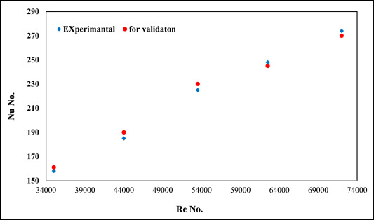
3.2. Validation of the program
The program was validated against a previous study [60]. The simulation conducted in the previous was similar to that conducted in the present study. Fig. 1 shows the relationship between the Nusselt number and Reynolds number (see Fig. 2).
 Fig. 1. Validation of Re and Nu numbers [60].
 Fig. 2. For Re = 14,000, convergence was used to solve discrete conservation equations.
3.3. Boundary condition
The positions of the boundary zone and the exterior and interior walls were defined within the same GAMBIT.
-
A.
Boundary Condition of the Fluid Entrance
The air intake flow velocity at a steady temperature of 300 K was estimated to be 5, 6,7, 8, 9, and 10 m/s.
-
B
Boundary Condition of the Wall.
-
C
In this study, 700 iterations were required to obtain convergence; this was because additional iterations were required for residuals that did not fall below the specified levels. Fig. 2illustrates the output iterations.
-
D
The Mesh for the Model.
Fig. 3 presents the grid-independent test, Fig. 4 presents the initial mesh that was made for the tube, and Fig. 5 presents the final mesh, which contained three million elements. Subsequently, the mesh settings were changed, and the number of elements was increased to ensure the best possible result. A grid-independent test was conducted for the third case at a low Reynolds number (1000). The test was stabilised at 3 million because any further increase in the number might have incurred additional costs and time and resulted in inaccurate results.
 Fig. 3. Grid-independent test.
 Fig. 4. Initial tube mesh.
 Fig. 5. Final tube mesh.
Fig. 6 shows a section of the ribs anchored inside the circular tube, and Fig. 7shows the mesh used for the solution (see Fig. 8).
 Fig. 6. Section of the ribs.
 Fig. 7. Mesh of the ribs used for the solution.
 Fig. 8. Geometry of the cooling fluid.

4. Results and discussion
In this study, both smooth and ribbed tubes were evaluated. Fig. 9-a shows the three-dimensional geometric shape of a smooth tube, and Fig. 9-b shows the three-dimensional geometric shape of a polygon tube.
The outside temperature was 673 K, the airflow temperature was 300 K at the intake, and the cooling airflow had a Reynolds number (1000–20000). The distribution of temperatures in the tubes with and without ribs is shown in Fig. 12.
 Fig. 11. A and b: passage in three dimensions. a) smooth circular; b) ribbed circular.
 Fig. 12. Temperature distribution in the absence and presence of ribs.
From Fig. 9, it can be inferred that the ribs increased the transfer of heat to the cooling air and increased the temperature of the air. In the third case, the cooling air was comparatively hotter because of the rib shape. The rib shape facilitated more air movement and more contact and friction with the inner tube surface. The ribs disrupted the core flow area (centreline) and created vortices, which improved the transmission of heat. A maximum heat core temperature of 378 k was observed at the end of the tube. The temperature of the cooling air near the traffic line increased significantly. Moreover, the ribs had a greater effect on the cooling air temperature at the wall, as shown in Fig. 5, Fig. 7.
Fig. 13 presents the tests conducted for the five Reynolds values. Initially, at the entrance to the AL, the temperature at the centre line of the tube was 300 K. Subsequently, the temperature increased along the corridor. In the case of the non-polygonal tube, an increase in the temperature was observed in the first, second, and third cases. The temperature was the highest for the third case, where the temperature of the cooling air was 378 K. Therefore, it can be concluded that the third case was the best case in terms of heat transfer. The heat transfer was primarily improved owing to the presence of the ribs, which led to the creation of eddies. Consequently, the heat transfer from the surface of the inner wall to the cooling air was improved. The presence of the rib in the first case led to an increase in the temperature of the cooling air by 6.25%, in the second case by 12.5%, and in the third case by 17%.
 Fig. 13. The numerical distribution of temperature at the centreline of the tube.
Fig. 14 presents the average values of the Nusselt number, which varied with the Reynolds number. The average values were calculated when the temperature around the wall was 673 K, and the cooling air temperature was 300 K. The Nusselt number increased with increasing Reynolds number, and the maximum heat enhancement occurred at a Reynolds number of 20,000. The Nusselt number was higher for the cases with sides. The third case exhibited a maximum average Nusselt number of 95 and Reynolds number of 20,000; this was because the rib reversed the flow and disrupted the boundary layer, which enhanced the heat transfer process. Therefore, the third case can be regarded as the best case.
 Fig. 14. The numerical relationship between the average Nusselt number and Reynolds number.