1. Introduction
1.1. Context and problem statement
The global response to climate change requires a far-reaching transformation across the energy system. Wind is currently the fastest growing source of renewable energy, with year-over-year growth of 53% (Lee and Zhao, 2021). Even though land-based installations dominate, offshore wind capacity expands ten times as fast as its onshore counterpart (Lee and Zhao, 2021). Owing to ever-larger rotors and more consistent wind speeds, offshore wind also provides higher capacity potential, enough to cover the current total world’s demand for electricity.
One of the main limitations of offshore wind farm development is water depth; when exceeding m, bottom-fixed foundations may no longer be economically viable (Myhr et al., 2014). With the development of floating offshore wind turbines (FOWTs), it is possible to remove the water depth constraint and harness large untapped wind resources far from shore, at higher operational efficiency and increased capacity factors (Johnston et al., 2020). Additionally, FOWTs have the potential to offer reduced installation cost, smaller seabed footprint, and less visual intrusiveness (Lee, 2005, IRENA, 2019). However, since the technology has not matured yet, the Levelised Cost of Energy (LCoE) related to these turbines remains high (Ghigo et al., 2020). A significant reduction of the cost cannot be achieved by a single innovation but requires a series of coordinated efforts in many disciplines (Evan et al., 2020, Barter et al., 2020). The success of FOWTs depends on advances at each stage of the turbine’s life cycle, including installation, operation & maintenance, and decommissioning. However, continued improvement in design and manufacturing is a key cost-reduction driver (European Commission, 2021). Between % of the capital cost of a FOWT can be attributed to the support structure (Gentils et al., 2017, Mathern et al., 2021). Therefore, as noticed in multiple references including Myhr et al., 2014, Mathern et al., 2021, Tran and Kim, 2017, Wang et al., 2022, the development of accurate simulation and optimisation tools is vital to the success of this technology.
1.2. Multidisciplinary design analysis and optimisation
Multidisciplinary Design Analysis and Optimisation (MDAO) is a field of engineering which focuses on the design of systems involving multiple disciplines and/or subsystems. Multidisciplinary optimisation is most useful in complex heterogeneous problems where the coupling between the multiple disciplines is too strong to be neglected, or where the synergy between subsystems can be exploited.
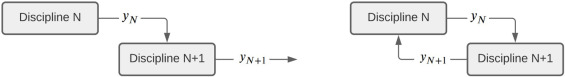
Such problems can be decomposed into a series of smaller blocks of computations, each with its own set of input and output variables (openmdao.org, 2021). The outputs of some of the blocks are passed as input to other components, creating either simple feed-forward connections or feed-back connections, which create a coupled model (Fig. 1).
A system containing feed-back connection(s), referred to as “Multidisciplinary Analysis”, needs to be solved iteratively to obtain unique and valid outputs, and only after all cycles (i.e., groups of computations with feed-back connections) in the model are converged, the outputs can be used to compute the design objectives and constraints (as detailed in Section 1.3), which are then fed to the optimiser block driving the solution of the entire MDAO problem, as schematically presented in Fig. 2.
 Fig. 1. An example of a feed-forward and feed-back schemes.
The way the particular disciplinary analysis components and cycles are grouped determines the hierarchy (or architecture) of the problem. A comprehensive review of many MDAO architectures developed was published by Lambe and Martins (2012), and the issues related to MDAO are extensively discussed in Agte et al. (2010) and Martins and Ning (2021).
 Fig. 2. General optimisation procedure.
Although applicable in all design stages, the MDAO of Floating Offshore Wind Turbines (FOWTs) is perhaps most effective at the conceptual design stage, when early decisions about the support platform topology are made. The knowledge gained in the concept phase is essential for the success of later phases, where any design changes can only be made at a relatively high cost (as illustrated in Fig. 14). As noticed in Safavi et al. (2016) and Barter et al. (2020), this is particularly true for complex, innovative structures with scarce prior empirical information. The physical environment and dynamics of FOWTs are very complex, with strong inter-dependencies between wind- and wave-driven responses (Bachynski and Moan, 2012).
The rotor nacelle assembly is primarily influenced by the aerodynamic loads, which in nature are nonlinear (the wind load varies with the square of the wind speed). The wind turbulence may excite low-frequency oscillations of the platform, blades and tower at multiples of the rotor rotational frequency (Lemmer et al., 2020). Additionally, the relatively low 1P frequency of the large 10-15MW rotors may overlap with the most energetic part of the sea spectrum, potentially magnifying the motion of the platform (Arany et al., 2016). The gyroscopic effect of the rotating rotor, which can be modelled as an additional damping term, affects the response of the entire system shifting the peak of the response spectrum to a higher frequency (Bahramiasl et al., 2018) and inducing a gyroscopic yaw moment (Jonkman, 2009). Inversely, the wave-induced rapid translational and rotational motion of the platform in the six degrees of freedom can substantially affect the tower-top motion, hence influencing the thrust and torque produced by the rotor (Karimirad et al., 2011) and the bending moments at the tower base and blade roots (Jonkman, 2007, Matha, 2010), subject to the action of the control system. Above the rated wind speed, the blade-pitch controller interacts with the platform pitch motion introducing the negative damping (Larsen and Hanson, 2007, Jonkman, 2008).
Traditionally, the floating support structures were designed to provide possibly the most stable, stiff platform for the tower and turbine adapted from bottom-fixed offshore wind turbines (Barter et al., 2020). The introduction of an integrated optimisation of the floating platform, mooring system, tower, rotor, and controllers allows to concurrently design the complete system, likely resulting in a less stiff and lighter substructure. To be able to study the cost advantages of the new configurations, economic modelling plays a crucial role. However, due to very limited experience with designing, manufacturing, installing, and operating these novel structures, cost components assumptions and models are subject to large uncertainties (Muskulus and Schafhirt, 2014). This indicates why the multidisciplinary approach to FOWT optimisation is not only justified, but necessary and challenging. Sufficiently advanced coupled models of economics, aerodynamics, hydrodynamics, structures, and control are necessary to capture all above-mentioned effects, while keeping the computational cost at reasonable levels (Bachynski and Moan, 2012, Jonkman, 2009).
1.3. Optimisation problem formulation
Many of the engineering design optimisation problems, including that of a FOWT system, can be classified as constrained multiobjective problems, with the following widely accepted mathematical formulation (Agte et al., 2010):
(1)
A multi-objective problem aims to optimise more than one design attribute. Several methods for combining the component attributes into one expression exist, one of the most often utilised being the Weighted Sum Method where the final cost function () is a weighted sum of the component functions (Zadeh, 1963). It is a matter of judgement to set these weights to reflect the importance of the chosen attributes (Arora, 2017). Other approaches to multi-objective optimisation exist, such as physical programming (Messac, 1996), or lexicographic method (Behringer, 1977). A comprehensive review of such methods is available, for example, in Arora (2017).
When considering a structural optimisation, the design vector () contains the geometric/material features of a structure, which are varied to result in different candidate designs, with lower and upper bounds (, ). The larger the vector of variables, the broader range of designs can be represented with a greater level of detail. However, an increasing number of variables leads to the so-called curse of dimensionality (Chen et al., 2015): as the number of variables (‘dimensions’) increases by , the size of the search space increases by a factor of , provided is the number of values considered for each variable. Therefore, significant simplifications are often necessary. Parameters () influence the behaviour of the system but are not controlled by the optimiser and cannot be freely chosen (material properties, operating conditions, etc.).
The collection of feasible designs is often referred to either as a feasible set or feasible design space. It is defined as a set of points that satisfy all inequality and/or equality constraints of the problem (Arora, 2017): and functions in Eq. (1), respectively. These constraints can be relative to the design variables (bounds) and/or performance of a system/subsystem (system constraints), and may vary in mathematical nature (linear/ nonlinear, explicit/implicit), which influences the choice of the optimisation algorithm and its performance.
In search of the best of all feasible solutions, two approaches can be distinguished: local and global (Arora, 2017). The most often followed practice, in the field of optimisation of floating structures, is to look for a local optimum, i.e., for a design that cannot be further improved by exploring its close neighbourhood (Arora, 2017). Unless one deals with a convex problem, the existence of a global optimum cannot be, in general, guaranteed (Arora, 2017). In an engineering approach, the goal is to find a much-improved design with the resources given, rather than looking for a globally-optimum design.
Article overview
The organisation of this article is as follows. Section 2 investigates the state-of-the-art implementations of MDAO frameworks in various engineering fields, including the design of FOWT support structures. Sections 3 Design variables, 4 Design objective/s, 5 Design constraints review the existing approaches to the selection of the design variables, objectives, and constraints, respectively. Section 6 reviews the most often utilised optimisation algorithms. Sections 7 Dynamic modelling, 8 Cost modelling investigate the selection of approaches to dynamic and economic models in FOWT multidisciplinary optimisation studies. The article is concluded with a critical discussion and recommendations for further improvements (Sections 9 Discussion, 10 Conclusions).
2. Multidisciplinary design analysis and optimisation
2.1. Development drivers
The cornerstone of MDAO was laid by Schmit (1960), who performed a fully automated optimisation to minimise the weight of a three-bar truss system by varying cross-section areas subject to constraints on stress, deflections and size of the members. The system was described by five simultaneous equations, where the displacements of the bars were related to the stress and temperature rise in the member, hence marrying the two disciplines.
The importance of integrated numerical analysis demonstrated by Schmit was well understood in the aerospace industry, where the introduction of composite materials triggered changes to the design process. Grossman et al. (1988)showed that the integrated aerodynamic-structural optimisation of a wing is superior to the traditional iterative design techniques. To account for the coupling between the structure and aerodynamics, two matrices were introduced into the system of equations: one representing the change in lift coefficient due to a unit twist angle, and one representing the change in twist due to a unit aerodynamic load. These cross-sensitivity matrices were obtained through the method of small perturbations (for instance, by recording the change in lift due to a small increase in the twist of a section for a range of scenarios), at each step of the optimisation. Favourable interaction between the two disciplines was exploited through distributing the structural material such that large deformations did not reduce the aerodynamic performance (moving the centre of lift towards the root of a wing), hence relaxing the need for keeping the deformations small. Reduced torsional stiffness allowed for reducing the structural mass, increasing the overall performance of the wing in a way not attainable through a sequential design.
Consideration of more complex cases required computational methods to become more efficient. Three different approaches to that task can be distinguished. Firstly, multiple disciplines can be merged to form hybrid disciplines (e.g., structural control (Haftka, 1990), hydro-elasticity (Garg et al., 2017)). This way, simultaneous manipulation of design variables in several disciplines is possible by a single widely skilled analyst, reducing organisational difficulties. Another common approach is to lower the fidelity of the analysis at the conceptual level. For instance, Ripepi et al. (2018) developed a reduced order model to predict aero-elastic loads based on a linear aerodynamic modelcorrected with a small number of high-fidelity Computational Fluid Dynamicscomputations. This technique brought a massive reduction in optimisation time (Jayaram et al., 1992). The last approach focuses on decomposition and global sensitivity techniques. In that case, the problem is split into multiple subproblems (optimisation loops), each concerning small subsets of the variables and constraints, grouped at the global level (e.g., Concurrent Subspace Optimisation (Sobieszczanski-Sobieski, 1989)). This approach is particularly useful if the calculations can easily be run in parallel, provided parallel computing is available (Martins and Lambe, 2013). The workload can be distributed between specific analyst groups, which can be based in geographically distant locations. Finally, system-level optimisation can be performed with minimal changes to the disciplinary analysis codes, with efficient data exchange (Sobieszczanski-Sobieski, 1990). For instance, Subramanian and DeLaurentis (2016) decomposed their airport noise minimisation problem into three optimisations: that of aircraft subsystems, aircraft, and approach procedures, linking the three subproblems through their inputs and outputs into a hierarchical system design problem, as presented in Fig. 3.
 Fig. 3. Example of optimisation decomposition in aeroplane design, based on Subramanian and DeLaurentis (2016).
2.2. MDAO applied to offshore oil and gas industry floating structures
While aerospace engineering can be dated back to (the beginning of the development of military aircraft), the first floating offshore structure, Ocean Driller, was deployed half a century later (). Around that time, Boeing made its first transatlantic flight, and the first manned spacecraft landed on the Moon. With a less apparent need for multidisciplinary optimisation when considering offshore floating structures, the MDAO concept was not broadly applied in that field. Only a few studies employed formal optimisation algorithms for the hull design (e.g., Clauss and Birk, 1996, Jang et al., 2019).
Examples of multidisciplinary optimisation in this field are even more scarce. Perhaps the most advanced study of such type was conducted by Sugita and Suzuki (2016) who utilised the simulated annealing and genetic algorithm to minimise the weight of a TLP, subject to constraints stemming form different disciplines (mooring tension, platform offset and natural periods, structural stress). The analysis framework consisted of hydrodynamic analysis, structural analysis, frequency-domain global performance analysis, and weight estimation modules. All modules were called in a sequential manner, once per each optimisation iteration, therefore, the responses were not converged at the system level before being passed to the objectives and constraints evaluation block. Regardless, this study was a great step in the transition from a traditional design approach to a fully automated approach.
2.3. MDAO applied to floating offshore wind turbines
The design of floating wind turbine support structures differs from the oil and gas platforms in many aspects. One of the most important distinctions is the fact that, while for O&G offshore structures the aerodynamic loads constitute a small fraction of the total load, FOWTs are designed to extract energy from the wind, and therefore both wind and wave loads are significant. Despite this, initially, FOWT platforms heavily relied on the oil and gas industry legacy, with conservative designs.
The first study on multidisciplinary design optimisation of FOWTs was published by Sclavounos et al. (2008), based on the thesis of Tracy (2007). The dynamic performance analysis was decomposed into three modules: mooring system, the floating structure, and the wind turbine, with the characteristics of each discipline assembled into one equation of motion based on a linear spring–mass–damper system in the frequency-domain (as presented in Section 7.1). Because the mooring loads may be nonlinear over large displacements, the platform steady state offset was computed by the hydrodynamic module and then used as a linearisation point by the mooring module, so that the offset and stiffness were computed iteratively, as per the simplified diagram in Fig. 4. The remaining inputs to the linear system were computed in sequence.
After the world’s first FOWT, Hywind I (KARMØY), was deployed and proved to be a technically feasible concept, the research on support platforms gained more interest. Currently, the process of design and optimisation of these structures, and the urge to reflect the great complexity of the system within the optimisation process, better resemble the practices seen in aerospace engineering than the traditional offshore sector.

Fig. 4. Iterative approach to steady state offset and mooring restoring matrix.
Adapted from Tracy (2007)One of the most sophisticated approaches to integrated design optimisation has recently been demonstrated by Hegseth et al. (2020b). The authors optimised the Proportional Integral (PI) control system, tower, spar platform, and catenary mooring system in an integrated manner, by combining the structural and control state–space systems into a complete closed-loop aero-hydro-servo-elastic model, as per Fig. 5.
A modular approach was applied, with discipline-specific calculations performed by individual units of code, connected in a multidisciplinary network by feed-forward connections (with one exception of a cycle for the calculation of viscous damping, as explained in Hegseth et al. (2020b)). By increasing the controller gains, a reduction in rotor speed variation was observed, however, this was achieved at the cost of increased fatigue damage. The cost and performance of the designs obtained thorough the integrated optimisation were also compared to those obtained without varying the controller gains, showing superiority of the coupled approach over the simpler structural optimisation.
 Fig. 5. Assembly of the structural and control models in one closed-loop state–space system through input/output pairs: generator torque , blade pitch and rotor speed .
When constructing an MDAO framework, numerous challenges must be overcome, including the choice of the order of execution of the disciplinary analyses, the management of the flow of information between the components, the choice of the system solver (linear/nonlinear, monolithic/recursive iterators), and the integration with an optimisation algorithm. Efficient implementation of these aspects requires a very specific set of skills and is time-consuming; the formalisation of system specification and workflow automation may take as much as % of project time, according to the survey in Ciampa and Nagel (2016). In that respect, the open-source and commercial tools developed by third parties are very powerful, taking a significant part of the coding burden off. A brief review of the three chosen non-proprietary tools is given in the next section.
2.4. An overview and comparison of available MDAO tools
OpenMDAO is an open-source framework for efficient multidisciplinary optimisation developed by the MDO Lab (Michigan University) in collaboration with NASA. One of its main advantages is the efficient data (input/output) passing between components through variables promotion or connect statements, and a choice of system iterative solvers (Gauss–Seidel, Newton, and more). Highly valued is also its ability to efficiently calculate the total derivatives, either numerically (finite-difference or complex-step), or through analytic partial derivatives followed by the computation of total derivatives (through a direct or adjoint method). Hence, gradient-based algorithms can be applied to optimisation problems with a large number of variables and constraints efficiently. Being open-source, the code can be fully customised. Additionally, an interactive model structure visualisation tool is provided. An example of the application of OpenMDAO to FOWT optimisation can be found in Hegseth et al. (2020b).
DAFoam, developed at the MDO Lab, models multidisciplinary physics with OpenFOAM – an open-source multiphysics software. The tool can deal with a large, constrained design space through the implementation of an efficient discrete adjoint method for total derivatives computation. The package also includes a geometry parametrisation module based on the Free-Form Deformation scheme (more details in Section 9), which makes DAFoam one of the most comprehensive tools available. However, the framework only supports optimisation algorithms available in the python library pyOptSparse, and the choice of physics solvers is limited to those implemented in OpenFOAM. An example of the application of DAFoam to engineering optimisation can be found in He et al. (2019).
DAKOTA is a multilevel parallel object-oriented framework for sensitivity and uncertainty analysis, design optimisation and calibration, developed by the Sandia National Laboratory with contributions from the community. This toolkit allows interfacing simulation codes with iterative mathematical and statistical methods through an interface developed by the user as a script in any language. This implies that DAKOTA can be connected to any simulation code, provided that the code can be executed from a command line and performs its I/O through data files. A wide range of optimisation algorithms is available, including both gradient-based and derivative-free methods. Additionally, nested models and parallel computing can be enabled and easily managed. An example of the application of DAKOTA to engineering optimisation can be found in Xia et al. (2018).
The main characteristics of these tools are reported and compared in Table 1.
Table 1. The MDAO tools reviewed in this study.
| Code | OpenMDAO | DAKOTA | DAFoam |
|---|---|---|---|
| Reference | Gray et al. (2019) | Eldred et al. (2002) | He et al. (2020) |
| Language | Python | C++ | C++, Python |
| Gradient-based algorithms | SNOPT, IPOPT, SLSQP, NLPQLP, FSQP, PSQP, ParOpt, CONMIN | Conjugate gradient methods, SQP methods, Newton methods, MFD, Augmented Lagrangian method | pyOptSparse compatible solvers including SNOPT |
| Derivative-free algorithms | NSGA2, ALPSO | PS, Simplex, Greedy Search Heuristic, NOWPAC, EA, DIRECT, EGO | – |
3. Design variables
To be able to analyse the performance of a large number of designs in an optimisation environment efficiently, their characteristics must be represented with the smallest set of variables possible. At the same time, sufficient design flexibility (or detail) must be ensured to represent the topologies adequately. Hence, a trade-off between the richness of the design space and the cost of the optimisation process is observed.
An MDAO application requires a common set of variables that can be manipulated and exchanged among different disciplines. Ideally, the geometric model should also be smooth (shape modification should maintain a smooth geometry), provide local control, and short setup time. Unlike most of the geometric variables, the non-geometric features (such as material type, anchor type, etc.), and composition features (such as number of floaters, hull sections, mooring lines, etc.) often have discrete nature. Hence, the development of an efficient parametrisation scheme is a non-trivial task. See Samareh, 1999, Samareh, 2001 for an extensive review of formal parametrisation schemes.
The design optimisation of FOWTs followed a less strict methodology for shape parametrisation, with no record of any interest in efficient parametric modelling in the literature up to date. One of the most mature approaches was demonstrated in Hall et al. (2014), where the mooring configuration was defined in a formal mathematical way. The attachment of the lines to the hull was fixed, and the anchor positions were set to linearly vary with the parameter ranging from (i.e., anchor directly under the mooring attachment point) to (i.e., the horizontal distance between the hull attachment and the anchor of twice the water depth). Taut configurations were represented by the negative values of the parameter , as presented in Fig. 6. For a given platform design and water depth, this parametrisation scheme allowed to model a continuous range of mooring configurations with just one design variable.
Another detailed mooring system parametrisation was presented by Hegseth et al. (2020b) who included four variables: line diameter, depth of the fairleads below the water surface, the total length of the line, and the horizontal distance between the fairlead and anchor. The inclusion of the mooring attachment point location in the set of design variables allowed the observation of the important platform-mooring system couplings. The fairlead depth below the water surface was shown to strongly influence the surge-pitch coupled motion, therefore influencing the pitch response of the entire system.

Fig. 6. Example of mooring line profiles for the line shape parameters .
Reproduced from Hall et al. (2013).A very common approach is to only include the mooring line length and its orientation defined by two additional continuous parameters: the horizontal distance from the fairlead to anchor, and the angle of the lines with respect to a global coordinate system (Brommundt et al., 2012). Some complexity can be added by allowing the diameter of the lines to vary along the line length (Myhr and Nygaard, 2012) or by varying the material of each section of the line (Pillai et al., 2019).
Floating platform parametrisation is greatly based on the examples of structures from the oil and gas industry. A few classical concepts exist, with spars, TLPs, and semi-submersibles being the most popular (Leimeister et al., 2018). The geometry of each of the platform types can be uniquely defined by a different set of parameters. Therefore, the majority of the studies focuses on a chosen class, narrowing the range of free parameters down to a minimum.
The tower design is often represented as a truncated cone with variable base and top diameters and a linear distribution of diameters in between, keeping the hub height fixed (e.g., Hegseth et al., 2020a) or variable (e.g., Ashuri et al., 2016).
The hull is usually modelled as either a single axisymmetric body or an array of these. For instance, Hegseth et al. (2020b) modelled the spar platform with sections, each having a variable height, top diameter, and wall thickness. The scantlings of the floating structures are usually considered only approximately by augmenting the wall thickness (for example in Hall et al. (2013)) or material density (for example in Jonkman (2010)) to account for the additional mass of the internal steel members. However, when structural dynamics are included in a multidisciplinary optimisation problem, it is necessary to model these structures more accurately.
This was achieved, for example, by Hegseth et al. (2020b), who proposed to model the T-ring stiffeners inside each of the sections of the floater with additional variables: the thickness and length of the webs and flanges, and the distance between the stiffeners. To reduce the number of variables and the computational effort, the authors adopted a B-spline approach. By using control points, smooth distribution of these parameters along the depth of the floater was achieved, and the number of variables related to the stiffeners reduced from as many as to just .
In their later study (Hegseth et al., 2020a), the authors noticed that the optimum wall thickness was mostly governed by the necessity to withstand the hydrostatic pressure. Hence, provided that the detailed scantlings design is not of interest, wall thickness can be expressed as a function of depth, with no need to be included in the set of variables.
To dampen the heave motion in near-resonance conditions, heave plates are often used, particularly in semi-submersible designs.Gilloteaux and Bozonnet (2014) allowed the use of multiple heave plates, with their spacing and radius as design variables. An interesting decision was to consider the ratio of the plate radius to the column radius, making this variable nondimensional. Lemmer et al. (2017) additionally considered the thickness of the plates, showing that with thick plates the wave cancellation effect can be achieved, significantly improving the platform response in waves.
A unique approach was followed by the researchers at the University of Victoria (Hall et al., 2013, Karimi et al., 2017), where the design space covered a wide range of designs moving beyond the standard classification of the foundations. The eight-parameter scheme consisted of a single central cylinder (characterised by a variable draft, radius and taper near the waterline), accompanied by a variable number of outer columns (each characterised by a draft, radius, heave plate radius and distance to the central cylinder). Such an approach brings along multiple additional challenges, not seen when parametrising a single-class platform. The scheme must be able to represent both the existing design topologies, as well as those not yet seen. The optimisation framework must be able to deal with the possible discontinuities in the complicated design space, where multiple local minima are possible. On top of that, the distant types of geometries generated by the parametrisation scheme must be evaluated with one common analysis model with comparable accuracy (these challenges are further discussed in Section 9.1).
Another approach to the task of covering all support structure configurations and beyond was presented by Hall et al. (2014). The basis function approach removes the consideration of the physical platform geometry and works with hydrodynamic coefficients instead. Hydrodynamic characteristics of each candidate design () are represented as a linear combination of hydrodynamic characteristics of a set of basis platforms (), as given by Eq. (2): (2)where the hydrodynamic coefficients may or may not be functions of angular frequency, .
The optimisation problem is defined in such a way that the objectives are achieved by varying the coefficients of combination (or weights) , which represent how much the final design resembles each of the basis designs. The final design is then reproduced by superposition of the basis geometries (no standard way of doing this exists). This approach avoids the requirement of expensive solution of the radiation and diffraction problems for every single design. Therefore, it offers a significant reduction in the optimisation time. However, ambiguity remains in the how these optimal combinations of basis functions should be translated to a physical geometry.
Note that the design of the fixed structural elements such as cross-bracings, tendon arms, ballast, fairleads, etc. was not discussed. Although essential for design integrity, such components are usually out of control of the optimisation algorithm and their parameters are chosen to fit the variable characteristics of each design. For an example of how these can be represented in a parametrisation scheme see Hall et al. (2013).
4. Design objective/s
Table 2 compares the design objectives, constraints, variables, and optimisation algorithms applied in the chosen 12 FOWT multidisciplinary optimisation studies. This section focuses on the review and assessment of design objectives.
Table 2. A comparison of the chosen elements of FOWT support structure MDAO frameworks.
| Reference | Sclavounos et al. (2008) | Fylling and Berthelsen (2011) | Myhr and Nygaard (2012) | Hall et al. (2013) | Hall et al. (2014) | Karimi et al. (2017) | USTUTT (2016) | Lemmer et al. (2017) | Dou et al. (2020) | Hegseth et al. (2020b) | Hegseth et al. (2020a) | Lemmer et al. (2020) |
|---|---|---|---|---|---|---|---|---|---|---|---|---|
| Objectives and constraints | ||||||||||||
| Economic | o | o | o | o | o | o | o | o | o | o | o | |
| Performance | o | x | ||||||||||
| Hydrodynamic | o | x | o | o | o | x | o | x | x | x | x | |
| Servo | x | x | ||||||||||
| Elastic | x | o | x | x | ||||||||
| Mooring | o | x | o | x | x | x | x | |||||
| Modal | x | x | x | x | x | |||||||
| Design variables | ||||||||||||
| Platform | x | x | x | x | x | x | x | x | x | x | x | x |
| Mooring | x | x | x | x | x | x | x | |||||
| Tower | x | x | x | |||||||||
| Cable | x | |||||||||||
| Control | x | x | x | x | x | |||||||
| Optimisation algorithms | ||||||||||||
| Algorithm | BF | SQP | B-A | 1 | 2 | GA | PSr | PSr | SQP | S+S | S+S | BF |
| Search goal | Global | Local | Local | Global | Local | Global | Local | Local | Local | Local | Local | Global |
| Gradient-based | x | x | x | x | ||||||||
| Derivatives | FD | A | A | A | ||||||||
x — criterion used as a constraint; o — criterion used as an objective; BF — brute force; PSr — Pattern search; S+S — SNOPT+SQP; B-A — BOBYQA; 1 — CMN GA; 2 — fminsearch; FD — finite-difference; A — analytic
4.1. Economic indicators
The economic viability of a given wind turbine design can be assessed based on the LCoE, defined as the ratio between the total life cycle cost (sum of discounted CapEx, OpEx and DecEx) and total energy production (AEP) (Castro-Santos et al., 2021). (3)Since this factor reflects the cost of a unit of energy produced, lowering its value is beneficial for electricity consumers and improves the competitiveness of wind energy in the energy market. Lower LCoE can be achieved by either increasing the energy production or reducing the costs of financing, manufacturing, installation, O&M, and decommissioning.
Most of the literature uses material weight and/or cost as a sole proxy for LCoE (Myhr and Nygaard, 2012, Karimi et al., 2017, Fylling and Berthelsen, 2011, USTUTT, 2016, Dou et al., 2020). Some positions also include the manufacturing costs (Hegseth et al., 2020b, Hegseth et al., 2020a, Lemmer et al., 2017) and the cost of anchors (Hall et al., 2013, Karimi et al., 2017). The inclusion of the anchor cost is important when more than one class of support structures is considered, as the gravity and driven anchors for TLPs can be twice as expensive as the drag-embedded anchors used with semi-submersibles and spars (James and Ros, 2015). An interesting approach was adapted by Tracy (2007), who used the displacement volume as a cost driver, noticing that this single, easy to calculate factor accounts for both the mooring system static tension and the structural mass, which largely influences the capital cost. A similar approach is proposed in Bachynski (2018), with the structural mass approximated as the product of the displaced volume and an empirical factor.
It is noteworthy that in the case of objective functions describing either the capital cost (such as those outlined here), or full LCoE (such as that used in Ashuri et al. (2016) for optimisation of bottom-fixed offshore wind turbines), it is relatively straightforward to ensure that the function is continuous, smooth and differentiable, what makes the use of efficient gradient-based optimisation algorithms possible.
The details of the economic models applied in FOWT multidisciplinary optimisation studies are discussed in Section 8.
4.2. Performance indicators
Floating offshore wind turbines must be both cost-effective and achieve the required response to ensure an efficient and safe energy extraction. For that reason, along with the cost, a series of performance objectives are usually considered.
Sclavounos et al. (2008) claimed the nacelle motion to be a critical performance measure. In this work, the standard deviation of the nacelle acceleration was expressed as an integral of the response spectrum (Eq. (4)): (4)
The authors argued that an excessive nacelle acceleration causes degradation of turbine performance and damage to the equipment. This metric was also considered important in Hall et al., 2014, Hall et al., 2013, Karimi et al., 2017, for slightly different reasons: large platform motions were thought to reduce the turbine lifetime, induce higher flapwise bending moments, and reduce energy production. The popular belief that the nacelle acceleration is of uttermost importance in FOWT design was challenged by Nejad et al. (2019), who found there that there is no correlation between the tower-top acceleration and drivetrain responses. The study also concluded that the tower top acceleration does not affect the rotor torque (and so the power produced) in any significant way, as long as the pitch control system remains intact (similar conclusion can be seen for example in Pustina et al. (2020) - this is discussed further in Section 9.2.2). Finally, although the fatigue life was found to be the dominating parameter for the main bearings, it turned out not to be influenced by axial nacelle acceleration. These findings were recently applied by Hegseth et al. (2020b), who decided to discard this objective from their study.
Sclavounos et al. (2008) demonstrated a multi-objective approach in which they aimed to minimise the nacelle acceleration, simultaneously minimising the mooring lines tension. A trade-off between these two objectives was exposed, showing that the minimum-tension designs (i.e., designs with catenary lines) were characterised by an increased nacelle acceleration. Myhr and Nygaard (2012) aimed to minimise the force value in the mooring lines as well as their weight using a time-domain approach. Pillai et al. (2019) performed an optimisation to investigate the trade-offs between the mooring system cumulative lifetime fatigue damage and its cost. Since mooring lines tension significantly influences both the dynamic behaviour of a wind turbine and the capital cost, the attention it receives in support structure optimisation studies is justifiable.
A different objective was considered in the study of Hegseth et al. (2020b), where the rotor speed standard deviation () was used as a proxy for power quality. For a given blade pitch angle, there is one optimum tip-speed ratio at which a turbine extracts the power from the wind most efficiently, i.e., at the highest coefficient of power (this can be seen in Fig. 7). Therefore, for best performance, the ratio of the rotor speed to the wind speed should be kept at exactly this value (all else fixed). Large variations in the rotor speed at a constant wind speed result in suboptimal operation. Additionally, variations in the mechanical speed of the rotor (and hence the generator speed) necessitate the voltage and primary frequency control (to meet the grid connection requirements), which result in major power losses (Anaya-Lara et al., 2018). The need to minimise the rotor speed variation was emphasised by numerous studies on control strategies, including Namik and Stol (2010).

Fig. 7. IEA 15MW controller regulation trajectory — variable speed variable pitch strategy.
Adapted from Evan et al. (2020).5. Design constraints
The classification of the criteria as objectives or constraints is not consistent in the literature, with the same criterion acting as an objective in one study and as a constraint in another.
For instance, the before-mentioned standard deviation of the nacelle acceleration, which was introduced as an objective in the previous subsection, was used as a constraint instead in Fylling and Berthelsen, 2011, Dou et al., 2020, Gilloteaux and Bozonnet, 2014. Rotor speed variation presented as an objective in Hegseth et al. (2020b) was instead used as a constraint in the later work of these authors (Hegseth et al., 2020a). It was observed that control systems can reduce these fluctuations, however, it is done at a cost of an increased blade pitch actuator use. Therefore, the control effort was included in the set of constraints as well. The threshold values for these two constraints were based on scaled values characteristic for bottom-fixed wind turbines (the matter of the use of various control systems to mitigate the consequences of the motion of a floating platform will be further discussed in Section 9).
Likewise, the mooring line tension is often treated as a constraint rather than an objective. Karimi et al. (2017) applied the minimum line tension constraint to avoid excessive slack in the taut mooring system, while Pillai et al., 2019, Hegseth et al., 2020b and Brommundt et al. (2012) set a maximum tension of the catenary line tension to avoid exceeding the breaking strength of the chains. The last two studies also constrain the loading on the drag-embedded anchors to be purely horizontal. This is to ensure the anchors remain effective, not being designed to take any vertical loading. The same goal was achieved in a different way by Pillai et al. (2019), who set a limit on the number of line points in contact with the seabed, and Dou et al. (2020), who limited the length of the suspended line to be not more than 75% of the total line length.
When the mooring system is subject to optimisation and both the taut and slack lines are considered, both the minimum and maximum line tension constraints are necessary to eliminate unfeasible configurations. This approach was followed in Tracy (2007) and Fylling and Berthelsen (2011). It is worth noting that the sum of the static and dynamic line tension should be considered to account for the worst-case scenario. For instance, Tracy (2007) formulated the maximum tension constraint as where – three times the standard deviation of the tension – represents the dynamic component of the tension. Similarly, the minimum line tension was formulated as — an approach easily applicable in frequency-domain frameworks.
A particularly useful constraint, which can be assessed early in the analysis process, is the avoidance of the resonance of the rigid body modes of oscillation with the environmental exciting loads. The full FOWT system must be designed in such a way that none of the important natural frequencies overlaps with the most energetic range of exciting frequencies. Here, the wind spectrum, wave spectrum, rotor and blade passing frequencies (1P and 3P) are to be considered, as illustrated in Fig. 8 for a 15MW reference turbine (Evan et al., 2020).
The intention behind this constraint is to avoid excessive motions. Often, this type of constraint is formulated more stringently by applying an additional % safety margin to account for the rotor speed variability and to ensure none of the system’s important natural frequencies is near these ranges (as shown by the lightly-shaded regions in Fig. 8). For instance, Myhr and Nygaard (2012) only discouraged the frequencies in the 1P and 3P ranges, while Ashuri et al. (2016) considered wider near-resonant regions (i.e., 1.9P – 2.1P and 2.9P – 3.1P).
 Fig. 8. Example frequency map for the IEA Wind 15MW reference rotor adapted from Allen et al. (2020). Red curve — Kaimal wind spectrum, blue curves — JONSWAP wave spectrum for a range of sea states. Dark shading for the main range, light shading for the safety margins of standard deviations. (For interpretation of the references to colour in this figure legend, the reader is referred to the web version of this article.)
In addition to the rigid motion modes, the resonance of the flexible modes (e.g., tower fore-aft, blade flapwise and edgewise natural frequencies) with these exciting frequencies (wind, waves, 1P, 3P) could be considered, to avoid augmented structural loads. However, this has not been considered in FOWT optimisation frameworks up to date, up to the best knowledge of the authors.
In the case of spar platforms, it is useful also to consider the so-called Mathieu instability. When the heave natural period is or 2 times the pitch natural period, the so-called internal resonance occurs, and the pitch motions become unstable (Rho et al., 2005). The constraint on the ratio between the two modes’ natural frequencies was used in Hegseth et al. (2020b). Although this instability has a low probability of occurrence, it is an important design consideration since when it does occur, consequences may be severe (Haslum, 2000). This constraint may be design-driving but is often neglected. Because many of the optimisation frameworks utilise linear frequency-domain models, they are not able to directly account for this nonlinear effect. Therefore, a constraint on the simple ratio of natural frequencies is a very useful and inexpensive addition to those models, to avoid the above-mentioned instability.
Other constraints applied in FOWT support structure multidisciplinary optimisation studies include the fatigue stress in the steel structure (Hegseth et al., 2020b, Hegseth et al., 2021) and mooring lines (Fylling and Berthelsen, 2011), the sum of the static and dynamic pitch motion evaluated in the maximum thrust condition (Hall et al., 2013, Gilloteaux and Bozonnet, 2014, Karimi et al., 2017), the standard deviation of the free surface elevation to avoid slamming and green water (Tracy, 2007, Gilloteaux and Bozonnet, 2014), maximum platform motion to avoid breaking the power cable (Brommundt et al., 2012), or maximum cable tension (Fylling and Berthelsen, 2011).
Table 3 lists the constraint limiting values assumed in FOWT optimisation studies. It is noteworthy that some level of ambiguity is seen in setting these limits.
Table 3. Constraint values used in FOWT optimisation studies.
| Constraint | Units | Limit | Optimisation study | Reference |
|---|---|---|---|---|
| Max static pitch angle | deg | 10 | Hall et al. 2013 | Hall et al. (2013) |
| 10 | Karimi et al. 2017 | Karimi et al. (2017) | ||
| Max static + dynamic pitch angle | deg | 10 | Tracy, 2007 | Tracy (2007) |
| 10 | Hall et al. 2013 | Hall et al. (2013) | ||
| 10 | Karimi et al. 2017 | Karimi et al. (2017) | ||
| 9 | Fylling et al. 2011 | Fylling and Berthelsen (2011) | ||
| 15 | Hegseth et al. 2021 | Hegseth et al. (2021) | ||
| 10 | Dou et al. 2020 | Dou et al. (2020) | ||
| 10 | Gilloteaux et al. 2014 | Gilloteaux and Bozonnet (2014) | ||
| Max RNA acceleration | m/s | 2.6 | Fylling et al. 2011 | Fylling and Berthelsen (2011) |
| 2.0 | Dou et al. 2020 | Dou et al. (2020) | ||
| 1.0 | Karimi et al. 2017 | Karimi et al. (2017) | ||
| 5.0 | Gilloteaux et al. 2014 | Gilloteaux and Bozonnet (2014) | ||
| Max horizontal offset | % of depth | 15 | Fylling et al. 2011 | Fylling and Berthelsen (2011) |
| 10 | Hegseth et al. 2020 | Hegseth et al. (2020b) | ||
| 15 | Dou et al. 2020 | Dou et al. (2020) | ||
| Min line tension (TLP) | kN | 0 | Tracy, 2007 | Tracy (2007) |
| 0 | Hall et al. 2013 | Hall et al. (2013) | ||
| 1000 | Myhr et al. 2012 | Myhr and Nygaard (2012) | ||
| 728 | Fylling et al. 2011 | Fylling and Berthelsen (2011) | ||
| 0 | Karimi et al. 2017 | Karimi et al. (2017) |
6. Optimisation algorithms
This section is not aimed at providing an exhaustive overview of all the optimisation algorithms available, but focuses on the algorithms that have been adopted in FOWT multidisciplinary optimisation studies.
The selection of an optimisation algorithm is governed by the consideration of the type of optimisation problem at hand, the search goal, and the search method. Like the majority of engineering problems, most, if not all, FOWT optimisation problems can be categorised as linearly or nonlinearly constrained problems. In some studies, the constraints are separated by introducing penalty functions, so that the use of unconstrained minimisation techniques can be made (e.g., Myhr and Nygaard, 2012).