1. Introduction
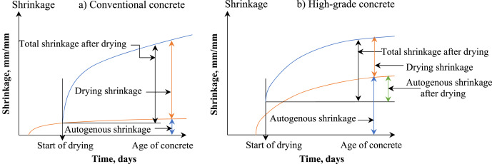
The formation of cracks in concrete structures increases their exposure to weathering attacks and decreases resistance to deterioration, thus reducing service life [1]. The mechanical performance of concrete-based infrastructure may also suffer due to cracking [2]. The shrinkage process occurs while the concrete hardens and is primarily responsible for crack formation. Specifically, concrete's contraction while still in a semi-liquid state is known as plastic shrinkage [3]. This naturally occurs in freshly placed concrete when the surface water evaporates before the concrete fully hardens. Plastic shrinkage cracking can occur if evaporation occurs faster than infiltrating water rises to the surface [4]. Therefore, during the time between the installation and when the concrete is completely set, the internal constraint of the surface plastic shrinkage could potentially result in the cracking of concrete surfaces [5]. In addition, exposing concrete to certain weather conditions, such as wet-dry and freezing-thawing cycles, can hasten the propagation of those cracks produced by plastic shrinkage on concrete surfaces [1]. Recent years have seen the emergence of environmental issues related to the production of Portland cement (OPC) [6]. Related to this, alkali-activated composite (AAC) has drawn great interest as a more sustainable alternative [7]. Ensuring AACs' long-term durability is critical to their adoption in the mainstream concrete industry [8]. Moreover, the performance of such OPC-free binders in terms of shrinkage and creep is one aspect that has attracted further research attention [9]. As an example, Fig. 1shows a schematic representation of the ratio of autogenous shrinkage to drying shrinkage that occurs throughout the total shrinkage of conventional and high-grade concretes (Fig. 1) [10]. Initially, the investigations conducted by Glukhovsky, who pioneered the utilization of indigenous materials for alkali activation, marked the inception of employing sodium silicate solution as an activator [11]. This practice remains prevalent in contemporary applications. Glukhovsky's novel approach involved amalgamating several types of fine soils, such as loess, sandy loam, river sand, ravine sand, loam, and brown clay, alongside industrial by-products like fly ash or slag. These materials were combined with solutions containing sodium hydroxide or sodium silicate, either with or without other substances. The materials utilized in the study consisted of soil silicates or foamed silicates. The initial formation of a cementitious substance involved the chemical reaction between sodium silicate and other additives, while solid precursors were employed as aggregates [12]. The resulting products of the reaction consisted of metal silicates that exhibited notable mechanical properties and long-lasting durability. Glukhovsky enlarged these elements for the construction project. The utilization of high-temperature curing in the second category of cementitious materials facilitates the dissolution of silicon (Si) from solid precursors, producing a silica anhydride with reduced solubility. Glukhovsky's research findings indicate that this particular approach has the potential to enhance the structural integrity of soils and effectively manage SiO2-rich waste materials that are dispersed [13]. The solidification process of the third category of materials involves the dissolution of aluminum (Al) and calcium (Ca) to produce N-A-S-H and C-A-S-H gels. These materials can be classified under geopolymers, alkali-activated materials (AAMs), or inorganic polymers [14]. For examples, Wallah and Rangan [15] reported the particular case of the effect of low-calcium fly ash-based geopolymer concrete by exhibiting minimal drying shrinkage, measuring around 100 microstrains over a period of one year. The aforementioned figure is notably lower when compared to the range of values between 500 and 800 microstrains for Portland cement concrete. In addition, to understanding alkali-activated materials by identifying and modeling alkali-activated pastes and concretes' rheological properties, including the impacts of novel water reducers, shrinkage controllers, foaming agents, and others [16].
 Fig. 1. Shrinkage in different concrete grads (Adapted with improvements from Ref. [10]).
The risks of shrinkage represented by cracking, deflection, and pre-stress loss can happen to concrete structures, affecting the structures’ durability and service life [17]. It is well known that high-strength concrete shrinks more than standard concrete does on its own, thus increasing the risk of failure of the concrete structure even under allowable loads [10]. Since over a half-century ago, there have been plenty of studies on predicting OPC binder shrinkage, creep, and durability [18]. Although numerous studies have assessed the hydration, microstructure maturation and mechanical properties of AACs [19], Few investigations have been undertaken on the shrinkage performance and mechanisms of these materials. Thus, the present research concentrates on the sustainable technology of AACs since it is necessary to know their durability features in order to expand the usage of AACs in the concrete industries (Fig. 2[20]) [21]. The shrinkage of AAC is an essential engineering characteristic that affects the likelihood of such a material cracking under constrained conditions [22]. Previous investigations showed that alkali-activated slag (AAS) shrunk more than OPC [23]. In addition, the type of activator and the amount of it [24], the particle size distribution of slag in terms of [25], and ameliorating circumstances [26] were found to be significant determinants in determining the shrinkage of AAS. However, limited studies have been done on shrinkage, principally the autogenous shrinkage of alkali-activated fly ash (AAFA). Meanwhile, it was shown that heat-cured AAFA mortar and concrete experienced significantly less drying shrinkage than OPC; samples of AAFA treated at room temperature experienced far slower drying shrinkage rates than those cured in a controlled environment [27].
 Fig. 2. Illustration of the sustainable technology used to develop the raw materials of alkali-activated concrete (Idea adopted from Ref. [20]).
Most studies on the plastic shrinkage process in concrete have determined that capillary stresses adjacent to exposed concrete surfaces are the main driving forces behind plastic shrinkage movements, which are usually caused by an imbalance between how fast they bleed and how fast they lose water [28]. Furthermore, Settlements made of plastic can affect how much concrete shrinks [29]. Most of the processes involved in shrinking plastic involve some physical activity [30]; whereas chemical phenomena may have an insignificant effect on the shrinkage of concrete in its plastic early age stage. Several investigations have been conducted to examine ways by which to minimize or avoid the development of cracks due to plastic shrinkage. In this regard, plastic shrinkage-reducing admixtures (SRAs) (Fig. 3) have been utilized to reduce capillary pressure by lowering the rate of moisture evaporation, resulting in the production of concrete with greater higher stability [31]. As for AAS, it has been reported that it can display significantly more drying shrinkage than OPC binders [32]. The high propensity of AAS for shrinkage and cracking has prompted numerous hypotheses. According to speculation, AAS binders contain a higher mesopore content (2–50 nm) than OPC, which could cause a greater degree of saturation to exist at any given relative humidity (RH), thereby leading to greater drying shrinkage [33]. Moreover, due to the AAS matrix's low elastic stiffness, drying causes significant shrinkage [8]. A previous study found that reduced pore size and carbonation shrinkage are potential causes of the significant drying shrinkage in AAS [34]. A time-dependent influence on the shrinkage behavior of AAS has also been reported; therefore, it is postulated that drying-induced creep is likely largely responsible for the extreme shrinkage of AAS [35].
 Fig. 3. Summary of the influence of SRAs admixtures in the relative drying shrinkage as reported by several researchers (Raw data obtained from Refs. [[36], [37], [38], [39], [40], [41], [42], [43], [44], [45], [46], [47], [48], [49]]).
To control plastic shrinkage cracking, the use of superabsorbent polymers (SAP) [30] or cellulose-based stabilizing agents [50] can decrease the likelihood of concrete cracking as a result of plastic shrinkage. Polypropylene fibers (PPFs) and other fibrous materials were also utilized [51]. To avoid plastic shrinkage, precautions should be taken during construction, watering down concrete, applying curing chemicals [52], or covering it with sheets to prevent moisture loss [53]. However, despite such efforts, concrete cracking due to plastic shrinkage remains a significant issue, especially when there are large, visible surfaces to repair or replace [54]. Various efforts and studies to mitigate the shrinkage behavior of alkali-activated slag-fly ash (AASFs) blends remain insufficient (Fig. 4) and efficient solutions have rarely been framed [55]. Nevertheless, a few studies have been conducted in this regard [19,56]. Some of these emphasized that for AAs based on FA, class F (AAFA) must be subjected to heat and steam curing for at least one day to effectively gain strength and avoid developing plastic shrinkage cracks within it [57]. According to the findings of previous researchers, Table 1 provides a summary of the effects of different supplementary cementitious materials (SCMs) and parameters on the shrinkage of AACs [58].
 Fig. 4. An diagram of initiated cracks as a result of stress development and controlled shrinkage (Adopted from Ref. [55]).
Table 1. Summary of the effects of different materials utilization in alkali-activated concrete and shrinkage parameters [7,51,[58], [59], [60], [61], [62], [63], [64], [65], [66], [67], [68], [69], [70], [71], [72], [73], [74], [75], [76], [77], [78], [79], [80], [81], [82], [83], [84]].
| Type of SCM | Year of publication | Type of expansive agent | Type of parameter | Content, % | Volume of alkaline dosage |
Activator 1. Na2SiO3 2. NaOH 3. KOH 4. CaO 5. K2SiO3 |
Type of alkali modulus, Ms | Curing condition | Compressive strength at 28-day, MPa |
Type of shrinkage 1. Drying 2. Autogenous 3. Carbonation 4. Chemical |
Recorded Shrinkage | Rate of reduction, % | Refs. | |||
| Max., με | Time, days | |||||||||||||||
| Temp., °C | RH, % | |||||||||||||||
| % | Na2O | |||||||||||||||
| SF | 2007 | PPFs | 0.1–0.3 | – | – | 3 | – | 20 ± 3 | 5% | 89 at 60 d | 1 | 2000 | 60 | 33–87 | [51] | |
| Slag | 2007 | PPG | 0, 1, 2 | 4 | 1 + 2 | 1–1.2 | 20 ± 3 | 55 ± 2 | 60–66 | – | 4240 | 180 | 7–36 | [59] | ||
| 2014 | Quick lime | EAs | 2, 4, 6, 8 | ∼14 | ✓ | 1 + 2 | 1.5 | 20 ± 3 | 60 ± 5 | 69–78 | 1 | 440 | 27 | 27–80 | [60] | |
| 2014 | MgOH | 2.5–7.5 | 4 | ✓ | 1 + 2 | 1.35 | 21 ± 2 | 50 ± 5 | 74–86 | 1 | 13,770 | 91 | 5–36 | [85] | ||
| 2014 | nano-TiO2 | 1, 3, 5 | 14.5 | ✓ | 1 + 2 | 1.6 | 20 | 95 | 62–75 | 1 | 950 | 28 | 12–46 | [61] | ||
| 2016 | Cross-linked poly acrylic acid | SAPs | 0, 0.3 | 4 | ✓ | 1 + 2 | 0–0.8 | 20 ± 3 | 50 ± 5 | 43–54 | 2 | 1130 | 20 | 56–70 | [62] | |
| 2016 | CCAA | SAPs | 0, 0.3, 0.6 | 4 | ✓ | 1 | – | 23 ± 1 | 100% | 25–29 | 2 | 200 | 28 | 60–75 | [62] | |
| 2017 | Gypsum | EAs | 3.8, 7.7 | 6 | ✓ | 2 | – | 23 ± 0.5 | 50% | – | 1 | 12,890 | 43 | −2, 1 | [63] | |
| 2016 | PPG | SRAs | 0.25–1 | 4 | ✓ | 1 + 2 | 1.85 | 23–25 | 50 ± 5 | 99–121 | 1 | 7240 | 24 | 6–82 | [64] | |
| 2017 | Microsilica | EAs | 5, 10, 15 | 15.5 | – | 1 + 2 | 4 | 22 ± 3 | 65 ± 5 | 43–72 | 3 | – | 28 | 16–34 | [65] | |
| 2018 | PPG | SRAs | 0, 0.5 | 10 | K2O | 5 | 0.78 | – | 50 | 65–67 | 1 | 4850 | 28 | 12 | [66] | |
| 2018 | PEG | 0, 1, 2 | 8 | ✓ | 1 | 2.1 | 23 | 50 | 115–129 | 1 | 4270 | 28 | 14–25 | [67] | ||
| 2018 | Alkyl polyether | 0, 1, 2, 3 | 4 | ✓ | 1 + 2 | 1.2 | 20 ± 3 | 60 ± 5 | 58–60 | 1 | 1970 | 56 | 35–44 | [66] | ||
| 2018 | Ca(OH)2 | EAs | 0, 5, 10 | 5 | ✓ | 1 + 2 | 1.2 | 20 ± 5 | 55 ± 5 | 58–41 | 1 | 1110 | 180 | 33–41 | [68] | |
| 2018 | CaO-type, CSAE | 0, 6, 10 | 4 | ✓ | 1 + 2 | 1.2 | 20 ± 3 | 60 ± 5 | 58–60 | 1 | 1970 | 56 | 43–54 | [66] | ||
| 2019 | MgO | EAs | 0, 3 | 4 | ✓ | 1 + 2 | 1.0 | 20 ± 1 | 50 ± 3 | – | 1 | 4160 | 56 | 25% | [69] | |
| 2018 | Ca(OH)2 | 5, 10 | 5 | ✓ | 1 | 1.2 | 20 ± 2 | 55 ± 5 | 41.3–67 | 1 + 2 | 1109 | 180 | 10–52 | [68] | ||
| 2020 | CaO | 0, 3.5 | 7.5 | √+ K2O | 1 + 3 | 0.48 | 20 | 60 | 93–97 | 1 | 3920 | 150 | 48 | [7] | ||
| 2020 | PPG | SRAs | 0, 0.5, 1 | 4.3 | ✓ | 2 | – | 20 ± 0.5 | 43 | 41–45 | 1 | 17,680 | 77 | 10–19 | [70] | |
| 2020 | Polyether | 0, 3 | 6.2 | ✓ | 1 + 2 | 1.2 | 20 | 50 | 86–88 | 1 | 8570 | 56 | 58 | [71] | ||
| 2019 | Nano-magnesia | NPs | 0, 1, 2, 3 | 3 | ✓ | 1 + 2 | 1.0 | 23 ± 2 | 50–70 | 27–70 | 1 | 4920 | 56 | 10–55 | [72] | |
| 2020 | CLCAA | SRAs | 0, 0.26, 0.51, 1 | 5–7 | ✓ | 1 + 2 | 1.5 | 20 ± 0.1 | – | 31–63 | 2 | 5970 | 7 | 54–58 | [73] | |
| 2021 | Sodium polyacrylate | 0, 0.3 | 4 | ✓ | 1 + 2 | 0.8–1.4 | 20 ± 1 | 100 | 45–57 | 2 | 5060 | 7 | 72–81 | [74] | ||
| 2020 | Ethylene glycol | SRAs | 0, 1.5 | 7.5 | √+ K2O | 1 + 3 | 0.48 | 20 | 60 | 81–97 | 1 | 3920 | 150 | 38 | [7] | |
| 2019 | Oxyalkylene alcohol | 0, 3 | 4 | ✓ | 1 + 2 | 1.0 | 20 ± 1 | 50 ± 3 | – | 1 | 4160 | 56 | 35–64 | [69] | ||
| Slag + FA | 2020 | Solution-polymerized | SRAs | 0, 0.16 | 6 | ✓ | 1 + 2 | 1.5 | 23 ± 1 | – | 62–76 | 2 | 3530 | 7 | 54 | [73] |
| Slag FA | 2019 | PEG | 0, 2.5 | 12 | ✓ | 1 + 2+3 | 3.96 | 22 ± 2 | 50 ± 4 | – | 1 | 1780 | 60 | 45 | [75] | |
| Slag + FA | 2016 | CaO | 1, 2, 3 | 6 | ✓ | 1 | 1.4 | 20 ± 2 | 60 ± 3 | 70–78 | 1 | 2180 | 56 | 7–17 | [76] | |
| Slag + FA | 2019 | Gypsum | 0, 2 | 12 | ✓ | 1 + 2 | 3.96 | 22 ± 2 | 50 ± 4 | – | 1 | 1780 (d) | 60 | 8 | [75] | |
| FA | 2019 | Hexylene glycol | 0, 2 | 20 | Dosage | 1 + 2 | 1.0 | 23 ± 2 | 50 ± 4 | 69–76 | 1 | 4650 | 56 | 37–38 | [77] | |
| FA | 2016 | Nano-TiO2 | NPs | 0, 1, 3, 5 | 8 | ✓ | 1 + 2 | 1.5 | 20 ± 3 | 90 ± 5 | 64–78 | 1 | 1040 | 28 | 12–49 | [61] |
| FA | 2017 | Hexylene glycol | SRAs | 0, 2 | 20–25 | Dosage | 1 + 2 | 1.5 | 23 ± 2 | 50 ± 4 | 49–70 | 1 | 5410 | 56 | 32–43 | [78] |
| FA | 2022 | CaO | EAs | 23.55 | 6 | ✓ | Na2O | 1.2 | 20 ± 2 | 60 ± 5 | 35–75 | 1 | 5000 | 28 | – | [80] |
| CG + slag | 2021 | HPC EA | EAs | 0, 3, 5, 7 | 8 | ✓ | 1 + 2 | 1.6 | 20 ± 2 | 60 ± 5 | 12–52 | 1 | 900 | 28 | 52–116 | [79] |
| CG + Slag | 2021 | Alkyl polyether | SRAs | 0, 1, 2, 3 | 12 | ✓ | 1 + 2 | 1.3 | 20 ± 2 | 60 ± 5 | 58–62 | 1 | 2720 | 180 | 26–47 | [82] |
| FA, GGBS | 2022 | NaOH, Na2SiO3 | SAP | 0.4–0.8 | 12 | ✓ | 1 + 2 | – | 900 | 60 ± 5 | 51–83 | 1 | 900 | 14 | – | [81] |
| OPC | 2022 | MgO | 2, 4 | – | ✓ | – | 1 | 20 ± 2 | – | 15–35 | 1 | – | – | – | [83] | |
| SF,OPC | 2022 | MgO | SRAs | 1.5, 3, 15 | 0.5 | ✓ | 1 | 0 | 20 ± 2 | 60 ± 5 | 25–46 | 1 | 2772 | 28 | 19 | [84] |
Annotations: Superabsorbent polymers (SAPs), Polypropylene glycol (PPG), shrinkage-reducing admixtures (SRAs), High-performance concrete EA (HPC-EA), Cross-linked copolymer of acrylamide and acrylate (CLCAA), Nano particles (NPs), Coal gangue (CG), Ethylene glycol (EG), Polyethylene glycol (PEG), Fly ash (FA), Calcium sulphoaluminate-type EA (CSEA).
Therefore, this paper scientifically reviews the shrinkage behavior of ACC and evaluates the common shrinkage alleviation strategies and their shrinkage-reducing mechanisms. Furthermore, it provides a critical evaluation of the shrinkage-reducing mechanisms, envisaged prevention measures, and areas that require additional research to comprehensively grasp the factors that influence shrinkage and investigate research strategies to encourage the development of renewable AAC composites. This paper also aims to identify the areas that require additional research to grasp the factors that influence shrinkage comprehensively and to devise research strategies to encourage the development of sustainable AAC composites. In doing so, limitations in terms of long-term durability against micro-cracking and shrinkage can be tackled, thereby facilitating broader industry acceptance of AACs as viable construction eco-products.
2. Shrinkage
Shrinkage is a significant factor for all cementitious systems; however, the OPCsystem is the one that has received the most research attention [82]. It is possible to divide concrete shrinkage into four distinct categories (Fig. 5 [86]): drying shrinkage [87], plastic shrinkage [88], carbonation shrinkage [89], and autogenous shrinkage [90]. Most of these are associated with Portland cement-based concrete, although they can also occur in cementitious systems, such as AA systems. Based on the shrinkage behavious of AAMs discussed by Radlinksa et al. [91,92], alkali-activated slag mixtures, commonly referred to as AAMs, have been shown to possess strength values comparable to those of regular Portland cement (OPC). However, it has been observed that these AAMs also display a heightened degree of autogenous and drying shrinkage. The augmented autogenous shrinkage of alkali-activated slag (AAS) may be ascribed to many causes, including reduced elastic stiffness, elevated saturation, and heightened chemical shrinkage. An inverse relationship exists between elastic stiffness and drying shrinkage, whereby a decrease in elastic stiffness is correlated with an increase in drying shrinkage. However, it is important to acknowledge that other variables, like reduced pore size and carbonation shrinkage, are likely to play a role in the observed elevated drying shrinkage in AAS.
 Fig. 5. The relative sizes/time of several categories of shrinkage.
2.1. Plastic shrinkage
Many researchers have investigated plastic cracking in unconventional concretes like AACs [1,93]. In this way, some researchers came up with the prediction, modeling, and numerical simulation of plastic cracking to understand better how cement-based materials crack plastically [94]. Their models and findings revealed that the consolidation of the solid components of concrete, which affect the bleeding, and the subsequent rapid loss of bleed water through the concrete's exposed surface, are the two main trigger mechanisms for the plastic cracking of concrete [95]. Furthermore, it has been confirmed that capillary shrinkage results from the development of high tensile capillary pressures inside concrete pores in a plastic state due to evaporation [31,95]. It has also been revealed that volume contractions are linked to particle consolidation and capillary shrinkage. For cases where steel reinforcement prevents such shrinkage [9,96]. Past studies have reported that the mechanics of plastic shrinkage may be accelerated or slowed down by several contributing factors; factors such as relative humidity (RH), w/c, admixtures, hydration heat, additives, and the size of concrete members are all important, concrete surface temperature, and the sharp change in surrounding atmosphere temperature [97]. Fig. 6 illustrates the concrete plastic cracking processes and associated phenomena [98].
 Fig. 6. Concrete plastic cracking phenomena and processes (Adapted from Ref. [98]).
Plastic cracking usually develops when the cumulative tension strain exceeds the plastic concrete's tension capability; plastic cracking typically ensues when the total tensile strain exceeds the plastic concrete's tensile strength [99]. Cracks developed by plastic shrinkage manifest as meshed or parallel damage patterns and can be as wide as 1 mm in width and as long as 50–1000 mm in length [100]. Various investigations have found that, compared with normal concrete, AAS experiences higher plastic shrinkage than OPC [92]. For instance, the plastic shrinkage rates of four different AAS mortars were tested using varied activator types and dosages. Their study established that AAS had lesser rigidity, finer pore structure, and up to six times more shrinkage than OPC [92]. Its high shrinkage is attributed to the increased capillary tension caused by AAS's finer pore size distribution compared with OPC [23,77]. The precise scientific justification for the high plastic shrinkage characteristic of AAS remains to be fully understood. The measured cumulative water loss rates after exposing Portland cement and AAC specimens to drying conditions over a 6-h period were 2.2% and 0.5%, respectively [1]. These reduced moisture loss figures indicate that free water in AACs is leaking minimally, thus leading to the development of higher internal stress and greater plastic shrinkage cracks.
2.2. Drying shrinkage
The drying shrinkage of AACs differs from that of Portland cement-based products due to various reaction processes [101]. Because AAC composites are more sensitive to moisture loss, concrete systems based on Alkali-activated binders (AABs) usually shrink roughly 3–6 times more than Portland cement-based binders [101]. At 28 days with 50% relative humidity, a typical value is 500 micro-strains [102]. To a greater extent than capillary pores, which are larger and initially empty, drying causes shrinkage because water is removed from the gel's pores (created during hydration) [103]. Since more water is lost through the paste's pores as its hydration level rises, more shrinkage occurs at higher hydration levels [104]. The effects of the different curing conditions are depicted in Fig. 7 [105].
 Fig. 7. Influence of the different curing conditions (Adapted with improvement from Ref. [105]).
Continuous drying will result in shrinkage, continuous wet curing will result in expansion, and autogenous shrinkage will only result from sealed curing [106,107]. With each cycle of alternate soaking and drying, swelling and shrinkage are likely to occur, with the overall impact depending on the mix [108]. The type of compounds generated during the activation and curing processes controls the drying shrinkage of AACs [108]. After testing the effects of the internal curing (IC) of AAS concrete, it was discovered that the drying shrinkage was reduced when fully saturated slag coarse aggregate was used instead of normal weight coarse aggregate. It is clearlt reportedy by Matalkah [1] that one study investigated how the properties of AAS concrete were affected by increasing the curing temperature and concluded that heat curing significantly reduced the drying shrinkage of AAS concrete [109]. Furthermore, the quantities of alkaline solution, porosity, and the degree of hydration were reported to be influential factors in the shrinkage actions [101].
As mentioned previously, the drying shrinkage increases with the rise in water content [110] as also reported by Matalkah [1]; however, the amount of water present is not the only factor determining drying shrinkage. One study found that drying shrinkage was reduced when the sand-to-slag ratio was increased [108]. In contrast, the ratio of water to cement is a crucial factor in determining the rate of drying shrinkage [103], in which the proportion of water to binder decreases, causing the drying shrinkage to increment too, on average, decrease in size as a result [111]. The primary effect of the drying process is a reduction in volume, which is caused by changes in the hydration product's physical structure and the porosity network. As a result, reducing the amount of binder and water content in AAS pastes and mortars can positively impact the drying shrinkage of the materials. That is because less water and binder are needed. There are two leading causes of AAC's more significant shrinking. For starters, alkali aluminosilicate hydrates have much free water that evaporates and contracts as they dry. Because of the changes in the pore solution, the AAC structure has a higher capillary stress, which results in larger drying shrinkage. Since drying shrinkage in AAC paste is affected by micro-cracks caused by water loss in capillary pores, increasing the W/B ratio increased drying shrinkage.
Drying shrinkage is also heavily influenced by aggregate size and has been examined in numerous studies [1]. Intriguingly, using finer aggregates improves mechanical performance while causing increased dry shrinkage. Previous work examined how changing the proportion of sand to silica fume in cementitious materials affected drying shrinkage [112]. Using finer particles improved mechanical properties while causing an increase in drying shrinkage [113], as shown in Fig. 8. This might be justified by expanding the total surface area, which increases the reactivity of binder materials, thus consuming more water to hydrate and producing higher gel pore content. Limestone aggregate has been found to reduce the mass lost during drying, thereby decreasing the rate of drying shrinkage [103]. The cement paste and limestone aggregate particles could be reacting chemically, explaining this phenomenon, which strengthens the weak interfacial transition zones (ITZ) [113]. Accordingly, the amount of shrinkage that occurs during the drying process of OPC-based concrete increases by increasing both the average specific surface area of binder components and the volume and structure of the pores. Utilizing finer slag aggregate can lead to higher drying shrinkage. Moreover, using higher reactive SCMs, such as silica fume, produces denser gels and greater capillary tension because of the water meniscus and, ultimately, greater dry shrinkage from the increased hydration products and gel pores [114].
 Fig. 8. Some of the identified general causes of drying shrinkage.
The degree of pore connectivity and porosity has a major impact on drying shrinkages [113]. The porosity structure of the compositions can be used as an essential indicator of drying shrinkage; because of its greater porosity, cellular concrete contracts at a rate 10 times faster than conventional concrete [88,113]. The relationship between the porosity distribution and drying shrinkage rate in cement-based materials was examined in certain investigations. Schubert, for example, introduced a correlation between moisture content and porosity in examining this phenomenon [115]. An additional study demonstrated that drying shrinkage was enhanced by the incorporation of sisal fibers into the matrix [116]. It has also been shown that special chemical treatments, such as 10% KOH or 6% KOH and 10% KOH, can control the effect of natural fibers like luffa on the resistance to cracking and drying shrinkage [103]. Using chemical treatments increases luffa fiber crystallinity, improves crack resistance, and slows drying shrinkage in reinforced formulations [117]. In addition, researchers showed that the rate of shrinkage in aerated concrete increases as the number of finer pores increases [118]. This is because the size and number of microporesaffect how much something shrinks when it dries [119]. Moreover, numerous investigations have shown that, in most cementitious compositions, the rate at which it shrinks as it dries could be proportional to its porosity [103]. Fig. 9a demonstrates that AAS experiences greater loss of moisture and shrinkage strain than OPC, which is consistent with Gibbs-Bangham hypothesis [120]. However, it was noted that the drying rate significantly impacts AAS shrinking behavior [121]. The Gibbs-Bangham shrinkage principles are violated because the estimated shrinkage strain can differ significantly despite the same level of loss of moisture at different exposed RHs (Fig. 9b).
 Fig. 9. Representation of the drying kinetics in the zone of constrained adsorptions and the release of converging pressure: initial condition, (b) following a drop in relative humidity (Adopted from Ref. [120]).
2.3. Autogenous shrinkage
Alkali-activated mortar (AAM) has been the subject of increasing studies [122]. AAM systems have been shown in one study to experience much larger amounts of autogenous shrinkage and drying shrinkage than OPC systems [123]. Additionally, The degree to which an AAM system contracts depends on several factors, such as the activator used and its concentration, and the conditions under which it is cured [124]. Different types of alkaline activators, as well as the effects of FA and slag quantities, have been studied about the shrinkage of AAFS compositions (paste, mortar, and concrete) [125]. However, only a few investigations on the shrinkage of AAFS have been published. According to one study, for instance, significant AAS and drying shrinkage would occur if the slag content of the AAFS mixtures was increased while the sodium silicate to sodium hydroxide ratio was decreased [78,122]. However, exactly how AAF systems undergo autogenous contraction is still a mystery [122]. Lee et al. [108], at 28 days, researchers looked into the autogenous shrinkage of AAFS pastes and mortar and found that the shrinkage was caused by self-desiccation rather than chemical shrinkage. It has also been demonstrated that AASF concrete experiences slower autogenous shrinkage development than AAS concrete [35,55,126,127]. As shown in Fig. 10a and b, there is a reasonable consistency between measured and computed stress evolutions in AAC when the elastic component of autogenous shrinkage and the relaxing of the stress over time are considered in the calculation [55]. However, the drying shrinkage of slag and high-calcium FA-based concrete is still greater than the respective AS rates of AAS and AASF concrete [128].
 Fig. 10. Computed stress in AAS (a) and AASF (b concrete using the concrete's elastic component of autogenous shrinkage (Adapted with improvement from Ref. [55]).
Reportedly, the effects of 99% relative humidity on AAM sample shrinkage (which can be regarded as autogenous conditions) decreased when SRA based on polypropylene glycol were added to water glass-activated slag mortars [59]. Including 1% SRA caused a ∼200 με expansion over a 25-day curing period. However, the expansion was reduced by increasing the SRA to 2%. Although the authors noticed some OPC sample growth, it was much more subtle than the AAS [129]. However, AAS volume changes are thought to be caused by various mechanisms, but researchers are divided on which ones are most important: autogenous or drying shrinkage [130]. It has been reported that the AAS pastes demonstrate higher cracking than Portland cement, even in conditions that prevent them from drying [131]. The current findings and claims are consistent with the hypothesis that this is partially caused by AAS paste's increased chemical shrinkage [132]. These micro-cracks can be attributed to the tensile stresses produced by chemical or autogenous shrinkage during the specimens' moisture-curing processes. This is consistent with research conducted by Bakharev et al. [133], who found that the crack intensity in the matrix phaserises as the ratio of silica to sodium oxide values increases [134].
It is common knowledge that the chemical shrinkage that occurs during the liquid stage is the cause of autogenous shrinkage in PC systems. As was stated earlier, as the material becomes harder, the amount of shrinkage caused by autogenous processes is reduced relative to the amount of shrinkage caused by chemical processes because the volume change resulting from autogenous shrinkage becomes more difficult due to the increased degree of restriction caused by the hardening of the hydrated cement paste [29,33]. Likewise, creating a skeletal microstructure restrains the contraction of chemical shrinkage, producing voids. In addition, Continuous hydration causes RH to drop and water molecules to curve more sharply due to changes in water molecule shape and pore emptying. The menisci's extreme curvature increases surface tension around the pore, compresses capillary hole and solid hydrate wall surfaces, and ultimately leads to a contraction in the hardened cement paste [[135], [136], [137]]. This is known as self-desiccation [138]. A higher rate of autogenous shrinkage would result from the increased curvature of the menisci and capillary due to the small diameter of the pores, so the theory goes [139].
However, the autogenous shrinkage mechanism that occurs in AAFS systems within the first 24 h due to a potentially distinct chemical reaction after casting the process after drying out could be unlike the well-known self-desiccation method [122]. Two primary reaction mechanisms of isolated AAM systems make up the alkaline reaction of AAFS, thereby making it a very complex process. Gel sodium aluminosilicate hydrate (N-A-S-H) and sodium hydroxide are the two most common byproducts of this reaction [140] using the AAF and C-A-S-H gel [141] from the AAS system do not undergo independent evolution, but rather undergo a shift in their structural and compositional structure [122]. Thus, to learn more about how AAFS pastes shrink on their own or autogenously, further investigations into autogenous shrinkage are required, especially immediately after casting.
2.4. Chemical shrinkage
Changes in composition result from chemical reactions; a material may undergo either chemical shrinkage or expansion, which indicates a quantitative shift in the amount of substance [142]. The dissolution of aluminosilicates causes shrinkage within the first few hours; After about 8 h, gels composed of Al-rich products form, expand, and then contract as the Al species polymerize further with available silicate oligomers to form a Si-rich network [143]. It is also found that when the Al species polymerize with the readily available silicate oligomers, a Si-rich network is formed, causing the material to contract. In addition, the RH drops and the curvature of water-air menisci increase due to continuous hydration because the water molecules shift and pores empty [144]. Meniscal curvature causes a compression of capillary pore walls and solid hydrates, which in turn increases surface tension and causes the hardened cement paste to contract [135,142]. This kind of drying-out process is referred to as “self-desiccation” [138]. This theory proposes that a tightening of the capillary wall and meniscal curvature result from pore diameters that are too small to accommodate the increased pressure; this would result in increased shrinkage [139]. There is a well-established link between chemical reactions and the shrinkage rate, and the amount of shrinkage is known to be directly proportional to the hydration level of the binder [145]. For instance, It has been shown that the chemical deformation evolution of metakaolin-based AAC (MK-AAC) differs significantly from that of OPC, which shows monotonic chemical shrinkage after casting [145]. It has been revealed that MK-AAC undergoes chemical shrinkage, physical growth and shrinking in the second, second, and third stages, respectively [143]. Recent studies, however, contradict that finding [78]; this idea of enhancing the hydration reaction in the presence of SCMs is at odds with the fact that a higher slag content would result in a smaller chemical shrinkage. The effects of varying alkali activator concentrations in the mixtures are likely to blame for the observed inconsistency.
Similarly, in the case of zeolites, and due to the small pore diameters, which are mostly in nanoscales, a significant portion of the volume contained within the water vapor diffusion channels inside the crystal is blocked or sealed off, which hinders the hydration process and result in lower chemical shrinkage [146]. Conversely, the inclusion of amorphous SCMs Si-rich creates mostly gel or capillary pores, with nanoscale diameters, due to their high reactivity [147]. In this case, it is unlikely that the pores could be clogged because of silica particles' high pozzolanic activity, which raises the hydration heat, hence formulating more capillary spaces and denser gels. Support for this opinion has been provided through an atomistic simulation, which showed that the geopolymer gel has less space between its molecules. Because of this, it is denser than crystalline zeolites like sodalite, which have been shown to have denser gels than crystalline zeolites [148]. Thus, the chemical shrinkage of MK-AAC in the later stages of polymerization may be attributed to the increase in tensile stresses on the capillary network of the pores, which in turn increases the stiffness of the microstructure [143]. Moreover, the slag's glassy structure causes a low atomic packing density in the un-hydrated material and is likely linked to the large chemical shrinkage seen in AAS hydration [132]. Researchers have found that the rapid self-desiccation of AAFA/AAS caused by a drop in internal relative humidity (RH) in the hardened mesopores is the primary driving mechanism behind this type of autogenous shrinkage (Fig. 11a and b) [108].
 Fig. 11. Chemical shrinkage of AAFS with different amounts of slag: a) AAFS = 0.1, 0.2 and 0.3; and b) Na2SiO3 -to-binder ratios = 0.12, 0.16 and 0.20 (Adapted from Ref. [108]) [Annotations: alkali activator (A) and slag (S)].
The mesopores comprised between 60 and 80% of the total pore volume compared with 36% in the OPC paste. According to another study, around 90%–95% of the total pore volume in AAS is composed of mesopores [23]. The effects of chemical shrinkage may be compounded by the fact that AAS pastes form with a decreased permeability. This prevents water from penetrating the specimens' interior while curing in a saturated environment (underwater), which in turn causes differential stresses that may result in cracking [131]. Briefly, autogenous shrinkage is caused by chemical shrinkage, which occurs when the volume occupied by the products of the reaction is less than that of the initial reactants. It refers to the stage at which AAC develops a sturdy skeleton to resist chemical shrinkage.
2.5. Carbonation shrinkage
Carbonation is one of the main issues with the durability of reinforced concrete structures. A reaction between two different substances is what brings about this process by CO2; the calcium hydroxide and calcium silicate hydrate gel are two examples of hydration products that can seep into pores [11], which raises the probability of corrosion in steel bars by lowering the pore solution pH [149]. Accelerated testing has revealed that the carbonation of alkali-activated binders could be a severe issue in some crucial applications, with laboratory experiments frequently revealing rather high carbonation rates [150]. However, AACs that exceeded the specific service age have not typically displayed carbonation-related issues [151]. This implies that, in contrast to OPC-based systems, the accelerated test results do not accurately anticipate the actual performance of AACs [152]. Thus far, only a few studies have attempted to characterize the parameters contributing to AAC carbonation [153]. These parameters include precursors, the activator's type and dosage, the concentration of CO2, and similar phrases, referring to an environment's relative humidity. Furthermore, a recent study [154] explored the influence of the slag/FA ratio on the carbonation-induced phase change in Na2SiO3-activated cement systems and found that a good slag/FA ratio could make reaction products more resistant to carbonation [155]. However, the process by which the silicate modulus of Na2SiO3 activators (Ms, SiO2/Na2O molar ratio) It is unknown how the factor in question affects the carbonation process.
Few studies have been done that focus solely on the carbonation of these systems and have been carried out under various exposure conditions, with concentrations of carbon monoxide ranging from one percent to one hundred percent [156]. However, there are still unanswered questions about the frequency with which this second step occurs in AAFA binders, as the Ca content in gel phases is in the minimum phase [157]. Although the durability indexes, including carbonation, are based on the porosity and permeability of AACs and OPC, their carbonation mechanisms are still distinct. For instance, In terms of carbonation, dissolved carbon dioxide in the pore solution may react with AAC reaction products, resulting in a decrease in the pore solution pH and an increase in the potential for reinforcing steel to corrode as a result of depassivation [158]. However, according to the findings of accelerated carbonation tests, the carbonation rate appears to be quicker than that of OPC because of the absence of calcium hydroxide in AAS systems. This information was obtained from several different reports [159]. Nonetheless, there is a possibility that the results of accelerated carbonation testing will not be relevant to the actual condition (0.03%–0.04% CO2) [160]. According to related literature, AASC has a natural carbonation rate that is only marginally ahead of OPCC in terms of speed [161]. Because of this, accelerated carbonation tests conducted cannot properly mimic the normal carbonation behavior of AAMs [[36], [37], [38], [39], [40]]. Several studies [162] have explored the carbonation of GGBFS-GPC and related geopolymer materials. This research reveals that geopolymer concrete has a higher carbonation rate than OPC while maintaining the same compressive strength; however, their carbonization mechanisms are distinct [163,164]. The higher carbonation rate of SCM leads to increased degradation in performance, resulting in a higher rate of compressive strength loss [164].
Related research has demonstrated that activators significantly alter the reaction kinetics of CSM materials [165]. For example, the rate of contribution of silica reaction in the case of the activated reaction differs with the variation of Na2O activator concentrations [166]. Furthermore, NaOH activation of the system results in a much quicker reaction time than Na2SiO3 activation [9]. On the one hand, compared to Na2SiO3-activated slag, slag that NaOH has activated has C–S–H gels that are more crystalline [167]; longer periods of hydration lead to the formation of a C–N–S–H structure that is enriched in sodium. On the other hand, the slag hydrates gradually in the Na2SiO3-activated system, which leads to decreased porosity and increased compressive strength while maintaining the same reaction degree. Even though it has been reported that hydrotalcite-like phases that share the same chemical makeup can be found in both systems [74], the formation of additional hydrotalcite phases is favored by the high pH of the NaOH solution [165].
In addition, carbonation depths in alkali silicate-activated slag concretes were between 13 and 25 mm after 240 h of exposure to 7% carbon dioxide [168]. Compared with the Na2SiO3-activated slag, the NaOH-activated slag is assumed to be more susceptible to carbonation due to the lower degree of reactivity and the denser C–S–H gel composition (Fig. 12a and b) [168]. It is found that when the Ms value reaches 1.0, there is a slight reduction in both the quantity of CaCO3 and the rate at which carbonation occurs. For concrete manufactured with OPC, 7 days of exposure to 4% carbon dioxide is roughly equivalent to one year of natural carbonation. The information serves as a point of reference [169]. This finding suggests that the accelerated carbonation test is approximately one thousand times more demanding on AACs than on OPC concrete [170]. Another investigation on carbonation rates in AAS/MK concretes revealed that the carbonation rate is also highly influenced by the carbon dioxide concentration employed during accelerated testing [160].
 Fig. 12. Content of CaCO3 and fitting curves in carbonated (a) AAS and (b) AAFS blended cements with various Ms (Adapted the average lines (reading) from Ref. [168]) [Annotations: mixture proportions of AACs (M) and slag (S)].
This can be ascribed to the increased leaching rate with rising CO2concentration, in which higher CO2 concentrations have a greater ability to filtrate into the capillary pore structure. Recent studies on the carbonation of AAS binders [150,171], Carbonation in highly alkaline solutions has been modeled using thermodynamic techniques [171], and has demonstrated that calcium-rich activated binders likely undergo a two-step carbonation process. The 1-st stage is the carbonation of the pore solution, which happens when the pore solution absorbs carbon dioxide from the air. As a result, the pH drops, and Na-rich carbonates eventually precipitate out of the solution [150]. The second step is when the dissolved carbonates react with the solid binder. This makes Ca-rich carbonates by partially decalcifying the Ca-rich binder phases [150].
Several researchers have been examining the carbonation phenomenon in the laboratory under various activated cementitious systems, including AAS, GGBFS-AAC, MK-AAC, and FA-AAC, as well as in various exposure conditions (CO2, RH) [171,172]. The results of the associated tests and the microstructural examination of the AAS concrete constitute the second stage and have revealed that this type of concrete system has higher durability, can serve for an extended period, and increases in strength over time [151]. Although studies on powdered pastes are useful in comprehending the carbonation mechanism of AAS, these studies cannot capture the impact of carbonation on the pore structure and mechanical properties of the material [173]. The most fundamental characteristic of cementitious systems is their pore structure. Thus, grinding reduces the capillary porosity, eliminating the mechanism leading to the collapse of the large gel pores [157]. The pore structure of the porous medium controls any diffusion mechanism that takes place within the porous medium.
Regarding the path taken by CO2 through the bulk paste of AAS, In the research that has been done, the pore structure's effect on the carbonation rate has gotten very little attention [157]. As seen in Fig. 13 [157], The conditions for accelerated carbonation did not accurately mirror the carbonation rate that took place in AAS concretes when they were subjected to natural conditions. In particular, less carbonation depth was found in AAS concrete after seven years of exposure in natural carbonation settings, with RH fluctuating between 70% and 76% and temperatures varying between 19 °C and 38 °C than was expected in places where carbonation happened more quickly (1% v/v CO2) [173]. The carbonation depth of the AAS paste activated with Na2SiO3 was somewhat less than that of the AAS paste activated with NaOH [174]. A smaller average pore size and smaller overall porosity are the results; the carbonation resistance of AAS mortars has been shown to increase with an increase in Ms from 0 to 2 [175]. The carbonation depth of AAS with Ms = 2.0 is larger than that of AAS with Ms = 2.4 due to a higher calcite concentration and enhanced capillary absorption [172]. The pore-blocking impact that prevents carbonation caused by calcium carbonate precipitation is microstructural degradation, such as decalcification of C-A-S-H gels and carbonation-induced microcracking, which has a lower impact [141]. However, When comparing the carbonation characteristics of AAS and FA-AACs, Ms has no significant impact [176]. Another investigation found that AAS concretes with MS values of 0.75, 1, and 1.25 all had equal carbonation depths. Additionally, using a phenolphthalein indicator to test the carbonation depth of geopolymer concretes revealed no discernible carbonation front [177]. According to a study, to a greater extent (more than 20% of the total depth studied), the pace of future carbonation is determined by the diffusion of dissolved carbon dioxide via the pore system of the carbonated concrete layer [157].
 Fig. 13. Fourier transform-infrared spectra of bulk AAS paste samples exposed to various environmental conditions (Adapted with improvement from Ref. [157]).
Compared with mortars made using Na2SiO3-activated slag, those made with NaOH-activated slag were proven more resistant to carbonation [162]. The decalcification of C–S–H was seen when Na2SiO3 was utilized as the activation in AAS mortars under CO2-saturated conditions led to a loss of matrix cohesion, a greater number of holes, and a 14% drop in mechanical strength after four months of carbonation. However, mortars' matrix cohesiveness rose, their overall porosity decreased, their mean pore size shrank, and their strength increased by as much as 93% [178]. A greater binder content (400–500 kg/m3) led to shallower carbonation for AAS concretes. Raw GGBFS's MgO content, for instance, was found to be strongly influenced by the binder chemistry in addition to the binder content. As a result, the carbonation behaviors in NaOH-activated slag cement and Na2SiO3-activated slag cement may not be the same due to the varied reaction mechanisms and products produced by these cement.
3. Reduction in shrinkage
A variety of scholars may be connected to the matrix type, SRA type, alkaline content, and curing circumstances to minimize shrinkage, which is the phenomenon of the volume reduction of the binders in the absence of external forces and at a temperature that remains constant. Shrinkage may be defined as the decrease in the volume of the binders. The significant shrinkage that occurs in alkali-activated systems is mostly due to including a high proportion of mesopores in pastes and the absence of crystalline phases (such as AFt, AFm, and CH) in the reaction products. These are the two primary causes. Several pozzolans may be used to lessen the shrinkage in AAC composites. This is because AAC compressive strength and it pointed out that it was due to the pozzolanic reactions of pozzolan. This is why, especially silica fume, slag and silica fume). Because of the pozzolanic reactions, the porous structure of the adhesive is compressed by the gel that is generated, which increases compressive strength.
3.1. Using alkali-activated composites
3.1.1. Alkali-activated slag
Alkali-activated slag (AAS), a potential substitute concrete system with lower emissions of CO2 than that based on OPC, has higher fire resistance and excellent mechanical properties [2,179]. However, unfortunately, autogenous and drying shrinkage contribute significantly to the high risk of cracking that prevents AAS from being used on a broad scale [180]. The substantial shrinkage of AAS has inspired the development of several different solutions, including compensating for the volumetric reduction with water or supplying additional volume to offset the effect of the volumetric reduction [2].
Because of its substantial shrinkage, AAS-formed C-A-S-H is likely a coagulated colloid or granular material with micro-defects. Because of AAS's granular nature, the time-dependent rearrangement and redistribution of C-A-S-H nanoparticles produce visco-elastic and visco-plastic shrinkage during drying. Thus, AAS reduces at high RH (N50%) because tighter nanoparticle packing compresses gel pores and refines pore morphology. C-A-S-H nanoparticles compress into smaller gel holes when subjected to capillary pressure. Micropores shut as drying continues, resulting in nitrogen-inaccessible zones. Because of C-A-S-H nanoparticle rearrangement, AAS deforms irreversibly. At high RH, stable capillary meniscus formation drives C–S–H nanoparticle rearrangement. When C-A-S-H nanoparticles collide and rearrange, Si micropores close. Previous research found that NaOH-activated slag was stiffer than OPC, which enhanced elastic deformation but not viscous characteristics. Due to the composite nature of cementitious materials, dispersed inclusions significantly impact their mechanical properties.
Among the proposed solutions is the inclusion of SRA and IC agents [47,59,62], which are the approaches utilized most of the time. Using IC agents like lightweight aggregates or SAP reduces mixing water demand (Fig. 14a) [59,62] and even nano-particles (Fig. 14b). This, in turn, reduces the capillary pressure brought on by the decline in RH [181]. However, the incorporation of IC agents could cause a reduction in the mechanical properties of AAS, especially in systems made up of lightweight particles, because of the porosity of these materials [47,62].
 Fig. 14. Summary of the influence of a) SAP admixtures [62,73,74] and b) NP admixtures [72,[182], [183], [184]] in the relative shrinkage ratio as reported by previous researchers.
SRA reduces pore solution surface tension, lowering capillary pressure and increasing relative humidity [185]. No effective remedy exists for AAS's natural attrition while drying, 10 times and 3 to 6 times higher than OPC levels [47,103]. Evaporation or transpiration might cause AAS to shrink [47,63]. The continual water consumption during the slag reaction lowers internal relative humidity and forms a water-air meniscus in the AAS, causing autogenous shrinkage [47,63]. Since the surrounding air has a lower RH than the AAS air, shrinkage happens during drying. As water menisci develop in pores due to evaporation, capillary tension increases [59]. AAS has higher drying shrinkage than OPC, restricting its usage in buildings [186]. The capillary pressure created by the pore wall's wettability in porous environments is also important [71]. The hydrophobic modification reduces capillary forces in porous materials, affecting liquid flow and evaporation [187].
Hydrophobic glass beads inhibit the capillary rise in a porous medium by 10 times compared to hydrophilic [188]. Under similar conditions, evaporation can be decreased by 75%. Hydrophobic compounds in cementitious materials prevent water infiltration and improve durability [189]. However, hydrophobic modification has not been shown to reduce AAS shrinkage [190]. Fatty acids, (polymeric) hydrocarbons, silanes, or siloxanes can make the substance hydrophobic [191]. Environmental concerns have led to studies on biotechnological methods for long-term hydrophobic agent production, considering natural materials' benign qualities [192].
Biofilms in concrete change its wetting behavior [71]. Previous research [193] shows that water evaporation causes volumetric instability and drying shrinkage. Like the wetting characteristic (Fig. 15a and b), biofilm content affects drying shrinkage and mass loss between 1% and 2%, although this influence decreases as biofilm content increases. Biofilm concentration reduces AAS drying shrinkage [71]. Drying shrinkage was reduced by 58.1% at 3% SRA, 59% at 1%, and 78% at 3%. Biofilm decreased AAS moisture loss. Fig. 13 indicates that 3% biofilm over 35 days reduces moisture loss by 73% [71]. The AAS biofilm has increased hydrophobicity, which lowers capillary tension and slows liquid flow [194]. Due to the difficulty of water absorption in hydrophobic porous media, its role as a hydraulic connector between the interior's saturated region and the exterior's evaporation zone is disturbed, reducing evaporation [195]. Meniscal development decreases capillary stress [69,193].