1. Introduction
Froth flotation was undoubtedly the most innovative and groundbreaking discovery for mining in the 19th century (Wills and Finch, 2015). Nevertheless, it did not last long that scientists recognized its limitations for extremely fine and coarse particles, which has remained a long-standing unsolved issue in the mineral processing field (Gaudin et al., 1931). From the early 20th century, many active companies applied the simplest solution to tackle this issue by increasing a flotation cell volume (Mesa and Brito-Parada, 2018), paying less attention to designing an efficient cell for the industrial application. In 2019, the largest mechanical flotation cell with a volume of 680 m3 (500 kW motor power) was installed in Dexing Copper mine (China) with a throughput of 30–100 m3/min (Yang et al., 2019). This strategy has been a matter of argument over many years. The present paper points this out by categorizing flotation cells into mainly two subdivisions i.e., fine and coarse flotation technologies. Since the meaning of fine and coarse particle ranges might vary from one ore type to another, particularly from sulfides to industrial minerals, a general perception is considered in this work.
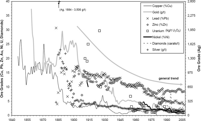
Nowadays, due to a reduction in high-grade ores, countries seek advanced dressing approaches for treating complex deposits and re-processing tailings to fulfill the requirements for minerals and metals in numerous industries. Fig. 1represents the cut-off grade for the base and precious metals (Cu, Au, Pb, Zn, Ni, Ag, U3O8 and diamond) over time in the Australian mining sector from 1840 till 2005. This indeed indicates that mining and mineral processing industries need highly efficient treatment processes and advanced technological support to effectively and selectively separate precious target minerals from gangues. Beneficiation plants must face up to several serious challenges due to falling mine cut-off grades, including substantial increase in throughputs, extremely fine grinding necessities, massive production of ultrafine particles, progressively dropping mineral liberation degrees, inefficiency of classification apparatuses, maintenance issues and deleterious consequences in downstream operating units such as flotation, leaching and filtration. In addition to tremendous energy consumption, environmental consequences in tailing damsinfluence mining industries dramatically. Lakshmanan and Gorain (2019)estimated that 10,000 million tonnes of waste is produced globally through the mining industries. For example, in the Kennecott mine in Utah, almost 100 and 200 million tonnes of respective ore and waste are handled annually (Ericsson, 2012). So far, the froth flotation technique is the most commonly applied physicochemical separation approach to the mining industry, which processes annually more than two billion tons of primary and secondary resources. However, in every industrial flotation-related process, a large amount of precious minerals is transferred to tailings in the form of extremely fine and coarse particles. According to previous reports (Bulatovic et al.,1998; Barkhordari et al., 2009; Yianatos et al., 2012, Agheli et al., 2018), in the case of copper treated in all operating concentration plants, nearly 50% of copper losses to tailings encapsulated either in particles finer than 20 µm or coarser than 150 µm (30–40% of lost). For instance, Fig. 2 illustrates copper distribution in the final tailing of Sarcheshmeh beneficiation plant. Considering copper alone, assuming an average loss of ∼10%, the flotation loss described could amount to at least 1.5 million tons per year, with a cash value of $10 Billion. The serious problem is that over 99% of mined materials in the precious metal industry are typically considered as a waste. Therefore, coarse particle flotation could allow mines to reject some waste earlier in the process before the fine flotation circuit, which can remarkably reduce capital and operating costs.
 Fig. 1. Schematic diagram on reduction of the cut-off grade of copper, gold, lead, zinc, uranium, nickel, diamond, and silver (Mudd, 2009).
 Fig. 2. Losses of copper to tailings for both fine and coarse particle sizes at Sarcheshmeh copper concentration plant (Hassanzadeh and Karakas, 2017).
Generally speaking, three key points push the mining industry towards coarse particle treatment, these are: i) drastic environmental consequences of wet tailings dams and acid mining drainage (AMD) (Glen et al., 2021), ii) losing precious materials in coarse fraction sizes (Safari et al., 2017), and iii) enormous energy consumption in comminution stages (2–4% global electricity usage) with less than 2% efficiency (Hassanzadeh, 2018). Although these concepts are well established, only a few technological developments have appeared in mineral processing industries over the last decades. The most recent industrial examples might be the commercialized rapid microwave and Nova Cell™. The former is a microwave (MW)-assisted grinding, which leads to a remarkable increase in material’s grindability, improvement of mineral liberation degree and reduction of the comminution energy by over 30% (Batchelor et al., 2017). Most research was carried out in batch conditions (Gholami et al., 2021, Fernandes et al., 2021) as a pretreatment process using a kitchen-type microwave except the recently fabricated and commercially utilized first industrial microwave operating at a throughput of 150 t/h (Batchelor et al., 2017). Some other industrial examples for different purposes were presented by Shaohua et al. (2018). However, its scale-up, modeling, and economic aspects have remained a matter of argument over the last three decades. The latter is an advanced flotation machine (Nova Cell™) which shows savings in operating costs of grinding energy and media by 40% and 12%, respectively (Jameson and Emer, 2019). This flotation cell drastically reduces the mining industry’s water and energy consumption by increasing the flotation's upper particle size limit. More detailed information regarding these technologies can be found elsewhere (Gholami et al., 2020, Jameson and Emer, 2019, Hassanzadeh et al., 2021).
Since the invention of froth flotation in 1905, numerous flotation machine designs have been proposed, particularly in the last 50 years. A detailed overview of the technological elaborations can be found elsewhere (Finch, 1995). Mechanically agitated devices, so-called either conventional flotation cells or tank cells, have been the most commonly used flotation machines in mining industries. They have been considered industry-standard using an impeller to mix solid–liquid-gas phases and maximize the particle-bubble capture efficiencies. Several geometrical properties of this flotation type machine were improved over the years by paying more attention to the impeller species, aeration types and cell sizes (Mesa et al., 2020). For example, the nextSTEP™ Rotor was recently designed by FLSmidth Inc to produce ideal flow streams, intensive turbulence to improve recovery rates and concentration grades. Application of computational fluid dynamic was introduced as a powerful tool for optimization and designing tank cells, however, validation of simulated data has faced some challenges as described in detail by Wang et al. (2018). Development in the aeration method includes self-aspirated cells such as the FLS Wemco, and compressed air cells e.g., the Outotec TankCell. The Recent advances in FLSmidth Inc. as a pioneer company in flotation processes can be classified into three groups: i) forced-air flotation machines (Dorr-Oliver) designed for recovering fine particles in terms of imposing high energy to these particles, concerning their low inertia in rupturing the water film; ii) induced-air flotation cells (Wemco), favourable for recovering coarse particles since these particles can be collected next to the surface and the travel distance of froth to the discharge lip is reasonably short; iii) forced-air and induced-air cells (Dorr-Oliver and Wemco), in a circuit with an idea of recovering both fine and coarse sizes using a combination of the two technologies in the same row/bank or different flotation stages (Govender et al., 2013).
1.1. Limitations of fine and coarse particle flotation
In an industrial scale, up- and down-stream operating units (e.g., grinding, classification and de-watering) inevitably affect metallurgical responses of a flotation process. Thus, the efficiency of either coarse or fine particle treatment systems is inherently coupled with the performance of these units. For example, the processing of rare earth elements (REE) embedded in carbonate, fluorocarbonate, phosphate, and fluorite deposits faces massive challenges concerning their extremely low grades, leading to being ground finely for achieving a desirable liberation degree (Azizi, 2018). Limitations in coarse and fine particle flotation have been fundamentally reviewed in a few studies (Trahar and Warren, 1976; Gontijo et al., 2007; Jameson, 2010; Farrokhpay et al., 2021) and briefly summarized in Table 1. Jameson (2010) presented theoretical backgrounds regarding the main difficulties in recovering ultra-fine and coarse particles. He developed the Concorde™ flotation cell and applied fluidizationprinciples to increase the recovery of ultra-fine (nickel sulphide and platinum ores) and coarse particles (galena) by a factor of ten. Farrokhpay et al. (2021)reviewed the existing approaches to overcome problems of fine particle flotation. The focus was mainly related to increasing the particle size by selective aggregation, decreasing the bubble size using sub-micron (nano)-bubbles, and introducing reactor-separator type flotation cells, which significantly promoted particle–bubble interactions. Awatey et al. (2013a)reported that the recovery of coarse particles was critically dependent on the froth stability, which was highly influenced by the overall particle size distribution of the feed material. They concluded that the recovery of single sphalerite and galena particles (>106 µm) decreased mainly because of the de-stabilization of the froth zone in a Denver® cell. However, Gontijo et al. (2007)observed that the stability of the bubble-particle aggregate controls the maximum floatable particle size of coarse quartz particles. In this context, Kowalczuk et al. (2011) presented an equation to maximize floating particle size in different flotation cells by considering particle and cell properties. As is clear from the literature, there is inadequate information concerning the technological developments on floating coarse and fine particles. Thus, the present work endeavors to fill this gap by considering fine and coarse particle flotation systems focusing on flotation cell types.
Table 1. Challenges of fine and coarse particle flotation (based on Trahar and Warren, 1976; Gontijo et al., 2007; Jameson, 2010; Farrokhpay et al., 2021).
| Fine particle sizes | Coarse particles sizes |
|---|---|
| Low mass | High mass |
| Low particle inertia | High particle inertia |
| Low particle-bubble collision efficiency | High settling velocity |
| Low attachment rate | High detachment rate |
| Low flotation rate | Low flotation rate |
| High specific surface area | Low specific surface area |
| High surface energy | Low surface energy |
| High surface oxidation | Low adsorption capacity |
| High adsorption capacity | Low mineral liberation |
| High reagent consumption | Low particle-bubble stability efficiency |
| High froth stabilization | Low froth stabilization |
| High entrainment | – |
| Solution | |
| High energy input | Low energy input |
| Small bubbles | Large bubbles |
| High froth depth | Low froth depth |
The main limitations in floating coarse particles by the traditional mechanical flotation cells are the low particle-bubble aggregation buoyancy and considerably high particle-bubble detachment rates (Table 1). A low particle-bubble stability efficiency (Es) originates from the centrifugal forces arising from the rotational motion of particle-bubble aggregates in turbulent fields (Gontijo et al., 2007; Hassanzadeh et al., 2019). The quiescent flow fields can prevent a high probability of particle-bubble detachment in a cell (Hassanzadeh et al., 2016). A poor liberation degree of coarse particles is another reason for their low kinetics rate and floatabilities (Hassanzadeh et al., 2020, Vallejos et al., 2021). Muganda et al. (2011) showed that the flotation rate increased rapidly with an increase in the contact angle for particles in the range of 20–105 µm, while only modest increases in the rate constants were observed for particles >300 µm. Additionally, poor suspension and low dispersion of coarse particles show limited particle-bubble collision efficiencies, leading to a reduction in the flotation kinetics rate and final recovery. Also, it is generally believed that coarse particles are vulnerable to the detachment at the pulp-froth interface during their transfer from the pulp to the froth zones. A few research studies showed approximately 2% improvement in the recoverability of coarse particles by distributing chemical reagents throughout the flotation circuit (Bazin and Proulx, 2001, Banerjee et al., 2007). It has been reported that since fine particles have substantially greater specific surface areas than coarse ones, they consume most of the reagents added into a flotation cell with higher adsorption rates (Hassanzadeh and Karakas, 2017). This results in an inadequate residual amount of collectors for floating coarse particles. All in all, coarse particle treatment by the conventional flotation machines is nearly impossible due to essential needs for a massive amount of energy for material suspension, high particle-bubble detachment probabilities, and low retention time.
Fine particles need less collector dosage and longer flotation time than coarse ones. Longer residence time is related to the low rising velocity of bubbles with attached particles, which results in a requirement for a substantial volume of flotation cells. Another issue concerning the poor floatability of fine particles is attributed to the low lifting force of small bubbles. Furthermore, it has been observed that microbubbles cause high water recovery leading to an increase in the entrainment of gangue minerals (Ahmadi et al., 2014). As time passes in a flotation process, the bubble size becomes larger due to reducing the reagent concentration in the slurry and dropping the solid content in the cell (Hassanzadeh et al., 2017). Poor recovery of fine particles is mainly related to the high specific surface area, high surface energy, low particle inertial force (Kouachi et al., 2017) and most importantly, low frequency of collision between particles and bubbles (Zpb) (Trahar, 1981, Safari et al., 2014; 2018; Hoang et al., 2018). In addition to that, Muganda et al. (2011) reported that the critical contact angle, below which flotation does not occur (Scheludko et al., 1976), for floatability of mineral particles varies with the particle size fraction. Fine particles less than 20 μm showed a critical contact angle of ca. 71°, while for particles above 75 μm, the critical contact angle increased with the particle size fraction. Technically speaking, to improve floatability of fine particles, one must either increase the particle size or decrease the bubble diameter. In this regard, the particle size can be enlarged by flocculants, while the small bubbles can be generated via dissolved-air flotation, induced-air flotation, hydrodynamic cavitation, electro-flotation and microbubble generators. The most common belief is creating an intense turbulent environment to increase the particle-bubble collision efficiency (Ec), however, it is an extremely energy-consuming process (Schubert, 2008, Safari et al., 2017, Hassanzadeh et al., 2018). Other than those, it was indicated at the OK Tedi plant that sulphidization by NaHS could improve recovery of ultra-fine particles (<20 µm) in copper flotation up to 3.4% (Orwe et al., 1998). Shear flocculation and high-intensity conditioning (HIC) are other techniques used to increase the recovery of fines (Small et al., 1997). Mechanical vibration and acoustic wave pre-treatments are also reported as promising approaches to enhance the recovery of fine fraction sizes up to ca. 3.5% by a cleaning effect on the surface of the minerals and generation of heterogeneous nucleation of microbubbles on the particle surfaces (Nicol et al., 1986, Videla et al., 2016). However, no industrial installation has been reported for applied acoustic waves in the froth flotation processes yet.
Table 2 presents the technological varieties discussed in this work and their applicability in the particle size ranges studied. As is clear from the literature data, the process efficiency of conventionally used flotation cells drops significantly for fine/ultrafine and coarse particles. However, since such cells have been employed for many years in all flotation stages, and the risk of using novel cells for the mining sector is relatively high, they are still the industry preference. Another critical issue for restricting the applicability of pneumatic cells is scaling down and laboratory trials. Since the existence and design of batch-sized novel cells are limited, their scale-up procedure is based on the laboratory data given by the mechanical cells. Tabosa et al. (2020) described the scale-up procedure for the Jameson cell based on the flotation lab tests. The Jameson cell can be modelled using experimental data obtained by standard dilution cleaning tests on rougher concentrate streams choosing a fixed recovery value. Unlike traditional batch mechanical flotation tests, standard dilution flotation tests (developed by Glencore Technology to simulate Jameson cell performance through laboratory flotation tests), are carried out at a low solid content (ca. 10 %(w/w)) and with very low scraping rats to allow as much drainage from the froth as possible. Since performance of Jameson cells has shown as equivalent to three conventional cleaner mechanical cells, the test typically includes three cleaning stages. Despite their acceptance for the cleaning/re-cleaning stages, little proof of concept is provided in the literature for their favorable efficiencies compared to the mechanical cells in the rougher and scavenger stages. For instance, Pokrajcic et al. (2005) used experimental and pilot plant data to examine the potential existence of the Jameson cell as a scalper, producing final concentrate from the rougher feed (at Zinifex Century Zinc Mine) and pre-float cleaner (at Mount Isa Mines). An overall 2% improvement in the copper recovery and reduction of pyrite in the copper concentrate for Mount Isa Mines was reported. Another example is the recent pilot trials using Reflux™ flotation cell in rougher-scavenger stages at a North American copper mine (Dickinson et al., 2019). Therefore, it is essential to note that each technology can be potentially used for different purposes and even for broader particle ranges depending on the mineralogy, target floatable, and associated gangue minerals. As the current work focuses more on their main advances, detailed discussion concerning the role of slurry retention time, bubble size distribution, energy dissipation rate, gas hold-up, and superficial gas velocity will be presented separately in the future.
Table 2. Technological advances introduced in this work and classified into two groups.
| Technology* | |||||||||||
|---|---|---|---|---|---|---|---|---|---|---|---|
| Particle size | MFC | CFC | IGC | IVC | IHC | JC | OGC | RFC | SFR | FF | HF |
| Fine | ● | ● | ● | ● | ● | ● | ● | ● | ● | ||
| Coarse | ● | ● | ● | ● | ● | ● | ● | ||||
*Note: MFC: Mechanical flotation cell, CFC: Column flotation cell, IGC: Imhoflot™ G-cell, IVC: Imhoflot™ V-cell, IHC: Imhoflot™ H-cell, JC: Jameson cell, OGC: Oscillating grid flotation cell, RFC: Reflux™ flotation cell, SFR: Staged flotation reactor, FF: Flash flotation and HF: Hydrofloat™ cell.
The present paper aims to introduce technological barriers that the froth flotation currently faces, with a particular focus on identifying challenges and opportunities for treating coarse and fine particles. In case of coarse particle flotation, recent advances in several techniques including flash flotation and HydroFloat™ technology are introduced. For fine particles, both conventionally used mechanical and column flotation cells are comparatively discussed over the Imhoflot™, Jameson, oscillatory grid flotation cell, staged flotation reactor and Reflux™ flotation cells.
2. Fine flotation
2.1. Pneumatic cells
Pneumatic flotation cells, which employ airflow instead of using agitators as used in conventional cells, have been developed over the last few decades. One of the oldest pneumatic flotation technologies was commenced in the 1970s at the Bergbau-Forschung GmbH, Technical University of Clausthal, the Technical University of Berlin and KHD Humboldt Wedag (Bahr et al., 1970; Heintges et al., 1983; Alizadeh and Simonis, 1985, Imhof, 1988, Imhof, 2006). Unlike conventional tanks, pneumatic flotation cells are typically classified as high-intensity flotation machines with the capability of floating liberated minerals very fast, resulting in very short residence times, often half that of mechanical cells and a quarter of that of flotation columns (Young et al., 2006). One type of pneumatic flotation cells is the reactor-separator-based vessel. This pneumatic cell is typically composed of an aerator (so-called reactor or contactor) and a separating vessel (separator) (Mohanty et al., 2005). There are no moving parts for the generation of fine bubbles. The particle collision and adhesion to air bubbles mainly occur efficiently without the need for a conventional rotor–stator system in the aerator, which results in substantial energy savings. Therefore, a high fluid velocity is required to disperse the air into fine bubbles, increase the particle-bubble collision frequency and attachment efficiency, and maintain particles in suspension. The particle-bubble aggregates separate in the separator module, where the turbulence is much lower than in a conventional cell. This reduces the detachment and results in the mineral carriage to the froth phase.
The characteristics of the reactor-separator type flotation cells can be summarized as follows:
-
–
No moving parts exist for producing fine bubbles.
-
–
Particle-bubble collision and attachment occur in the aerator (forced bubble adhesion).
-
–
The aerator and separating vessel are physically separated.
It is well documented that pneumatic flotation units including column cells are more effective than the conventional cells in terms of recovering fine particles (Battersby et al., 2011). The pneumatic and traditional flotation cells differ concerning a requirement for compressed air and agitation, which allows substantial energy savings in pneumatic cells (Jameson, 2006; Young et al., 2006). Most recently, Safari et al., 2019, Safari et al., 2020a pointed out this by reverse flotation of iron ore utilizing mechanical, and two pneumatic flotation cells (i.e., oscillating grid and Pneuflot® cells). They showed that the pneumatic flotation cell had the best flotation performance under most operating conditions. Furthermore, Lima et al. (2018) addressed the same concept by comparatively analyzing mechanical and pneumatic devices for quartz flotation.
2.1.1. Column flotation cell
A column flotation cell (CFC) was invented in the 1960s but did not gain wide acceptance in processing base metals until the early 1980s. They are operated by introducing an ore near the top of the column and sparging air from the bottom, creating deep froth levels adding wash water from the top to remove entrained fine particles (Yianatos et al., 2005). The first commercial flotation column was installed at Les Gaspe (Quebec, Canada) in 1981 for molybdenum cleaning recognizing that one stage of the column could replace seven stages of conventional (mechanical) cleaning cells (Finch and Dobby, 1990). Since then, the technology has gained popularity, particularly in base metal and coal applications. The advantages of these devices include low installation, operating costs, and the ability to operate at high froth depths, allowing the production of significantly higher-grade concentrates compared to the conventional cells. Although column cells have achieved many successes in industrial installations, they still suffer from two inherent flaws. Firstly, coarse particles have significant settling velocities, which tend to have a shorter residence time in the cell, leading them to be hardly recovered. Secondly, fine particles generally lack the inertia to overcome the streamlines around bubbles and are less likely to collide with approaching bubbles (Zahab Nazouri et al., 2021).
CFCs are used industrially less than the mechanical cells mainly located in cleaning and re-cleaning stages. At this flotation stage, they significantly improve the grade by the counter-current fluid flow of air bubbles and pulp with a relatively long slurry retention time and the massive amount of wash water (Wills and Finch, 2015). However, the recovery of fine particles using such cells is relatively low due to the formation of large bubble sizes (>1.5 mm), low turbulence (quiescence fluid regime), and limited gas hold-up values (5–20%) (Finch, 1995, Finch, 2021). This was evidenced for molybdenum in the Codelco Andina copper pilot plant where the Mo recovery of 10–25% was obtained by the column cells while it equalled 40–80% using the Jameson cell (Morin and Lawson, 2016).
One critical factor in selecting a cell relates to the carrying capacity typically measured as the mass flow rate (t/h) of concentrate per cross-sectional (m2) of the surface area of the flotation cell. Since the number and size of the generated bubbles in column cells are respectively lower and larger than both mechanical and Jameson cells, they show low carrying capacities. For instance, Fig. 3demonstrates mean bubble sizes measured by an identical technique (McGill bubble viewer) for mechanical, column and Jameson cells. As seen, two tested column cells exhibit the largest bubble sizes (db > 2 mm) compared to mechanical cells (0.7 mm < db < 2.7 mm) and a Jameson cell (0.5 mm < db < 0.7 mm). A detailed comparative description between column and Jameson cells can be found elsewhere (Huynh et al., 2014).
 Fig. 3. Comparative demonstration of bubble size in the mechanical, column, and Jameson cells (Huynh et al., 2020).
2.1.2. Jameson cell
There have been about 350 Jameson cells installed in various coal (especially in the Australian coal industry), metalliferous and industrial mineral applications worldwide (Osborne et al., 2013). The Jameson cell was firstly installed at the Mount Isa lead–zinc concentrator in 1988–1989 and successfully recovered fine particles (d80 = 12–15 µm). A comparison between mechanical, column and Jameson cells was presented by Harbort et al. (1994), demonstrating a favourable grade-recovery curve using the Jameson cell with two cells in series. As seen, the Jameson cell provided the most satisfactory results for lead grades and recoveries compared to traditionally used mechanical and column cells. One significant reason for such improvement was attributed to the short flotation time (ca. 3 min), which prevented surface oxidation of finely disseminated particles. However, both mechanical and column flotation cells required longer retention times (i.e., 5 min and 20 min, respectively) leading to oxidation of particle surfaces and reduction of their hydrophobicity. In the Jameson cell, the pulp feed is introduced through a nozzle or an orifice plate into the downcomer leading to the formation of the jet (Evans et al., 1995, Fuerstenau et al., 2007, Ding, 2016). In the downcomer, the jet entrains the air outside the cell considering that the air pressure in the downcomer is lower than the atmospheric pressure. The jet also provides significant mixing of the pulp in the downcomer. The entrained air in the downcomer results in the formation of fine bubbles and effective particle-bubble collision. Thus, the Jameson cell is a low-cost alternative to a traditional column flotation cell for recovering fine particles as it does not need a compressor for pulp aeration.
It should be noted that the collection zone in this cell is much smaller than that in the flotation column. In the separation tank, hydrophobic particles attached to the bubbles are transported to the froth phase, overflowing into the concentrate launder. However, hydrophilic particles remain at the bottom of the separation tank. The entrainment of fine and ultrafine particles in the froth phase is reduced using the wash water system as if flotation columns.
An advantage of this type of cell compared to traditional mechanical cells is the intensive collection efficiency of particles in the downcomer and the generation of high amounts of fine bubbles (200–700 µm) (Harbort et al., 2002). Thus, the gas holdup in downcomers is typically much higher (ca. 40–60%) than that of a conventional flotation vessel (ca. 5–20%) (Atkinson et al., 2003). The capability of floating liberated minerals with much higher kinetic rates results in considerably shorter residence time, which is the main advantage of the Jameson cell. Huynh et al. (2014) presented the advantages of the Jameson cell over the column cell noting a total residence time of 2–3 min in the tank (for separation only) while it was reported > 15 min for typically used column cells. Following this, Harbort et al. (1997) estimated the residence time required for mechanical and Jameson cells for cleaner and scavenger flotation circuit at Philex mining corporation to reach equivalent metallurgical performance, which resulted in 30 min and 2.9 min, respectively. The values of mean residence time (MRT) are notably reduced by decreasing the separator tank volume (Harbort et al., 2002), which can be achieved with a smaller tank height or a smaller tank cross-sectional area. This change did not affect the downcomer residence time. Through this, a limited number of Jameson cells can replace a large number of mechanical cells. For example, Hudbay’s New Britannia operation installed 4 Jameson cells replacing 11 conventional cells and at Philex, 10 Jameson cells replaced 50 conventional cells to treat 900 t/h of copper, which delivered a 4% increase in recovery and Ozernoye zinc mine reducing 63 to just 19 processing 875 t/h (Moore, 2021).
The Jameson cells in base metal flotation increase the final grade and capacity issues of conventionally operated flotation cleaner circuits (Araya et al., 2013). In other words, they have cleaner-scalper duties to recover fast floating minerals, decreasing the size and capacity of the cleaning circuit. Higher recoveries through these cells were reported compared to the conventional cleaning circuit (Fig. 4). The Jameson cell was successfully operated in the cleaning stage to treat the porphyry gold-copper ore in Minera Alumbrera Ltd in Argentina, resulting in gold and copper recoveries (finer than 10 µm) of about 80% and 90%, respectively (Young et al., 2006). The design has also been extensively developed since its first introduction and modern Jameson cells consist of up to 20 parallel downcomers incorporating sophisticated slurry injection systems which maximize air entrainment.
 Fig. 4. a) Size-recovery performance in the lead cleaner circuit at the Mount Isa lead–zinc concentrator b) zinc size-recovery in the lead cleaner circuit (Young et al., 2006).
Jameson cells are also used for prefoliation to remove naturally hydrophobic gangue materials (e.g., talc, and carbon) from the concentrates (Pokrajcic et al., 2005). When the amount of fast-floating material is significant, these cells can also be used for rougher-scalper and roughing duties to produce a high-grade concentrate (Curry et al., 2010). As a result, one Jameson cell is used instead of several mechanical cells, significantly reducing the capital cost. Although the Jameson cells are used in base metal flotation, their main applications are in the coal industry to improve the flotation performance and decrease the size and capacity of flotation circuits. For example, eight Jameson cells replaced thirty-two mechanical flotation cells in the Goonyella mine in Australia in 1995, significantly reducing the flotation circuit's size and improving the plant's yield by 3.5% (Carretta et al., 1997). They can also be used to recover fine coal particles from tailings successfully.
Jameson cells are particularly effective in fine coal flotation and produce high throughputs. Their weakness lies in the short contacting time of slurry in the downcomer, which is usually in the order of 10 s. This means that weakly hydrophobic particles only have a limited opportunity to contact bubbles and be recovered successfully. Therefore, the cell design is thought to be best suited to the flotation of highly hydrophobic materials such as coal and chalcopyrite. In addition, the cells require a highly stable feed rate and good control systems to prevent fluctuations in the performance. However, this weakness was somewhat mitigated by incorporating a slurry recycle to stabilize the feed rate.
2.1.3. Imhoflot™ G-cell
The history and development of Imhoflot™ pneumatic flotation cells are well documented in several technical reports (Brown et al., 2001, Imhof et al., 2003, Battersby et al., 2005). Imhoflot™ cells have great success in coal, potash, magnesite and many other base metal applications like copper, molybdenum, zinc and reverse iron ore flotation using H-cell, V-cell and G-cell types, which have been described in detail elsewhere (Imhof et al., 2004, Mohanty et al., 2005, Imhof et al., xxxx, Imhof et al., xxxx, Imhof et al., xxxx). The commercialization began in the early 1980s. From a design perspective, Imhoflot™ type cells differ from the conventional cells in that the particle-bubble collision takes place outside of the cell, within the aerator (Battersby et al., 2011). Similar to column flotation cells, it does not require compressed air and agitation, which provides the opportunity of saving a tremendous amount of energy compared to the traditional mechanical cells. The energy input goes more directly into the particle-bubble collision, rather than energy being used to maintain the pulp in suspension as in mechanical cells. The slurry is pumped with enough fluid energy to produce intensive aspiration of air and rapid dispersion for efficient particle-bubble collision (Imhof et al., 2005). The method of self-aspiration of Imhoflot™ flotation is based on the well-known venturi principle. However, the patented design has a complex system of nozzles, impingement plates and gas hold-up mechanisms that generates a spectrum of fine bubbles. There are three different types of Imhoflot™ flotation cells; tangentially fed (G-cell), vertically fed (V-cell), and another type so-called H-cell, which is a combination of the V- and G-Cell into a single unit. The design of the Imhoflot™ cell type depends on the particle size being floated. The V-cell is generally used for floating intermediate and coarse particles, designed for high concentrate yield duties while the residence time is approximately 3 min.
The Imhoflot™ G-cell is favoured for flotation of ultra-fine to intermediate-sized particles with a very short residence time of approximately 1.5 min depending on the particle size and mineral characteristics i.e., mineral hydrophobicity, association, and liberation. The dynamic and centrifugal action improve the mobility of rising air bubbles, which promotes gangue disengagement whilst reducing gangue entrainment in the froth by keeping the pulp-froth interface low in turbulence. G-cells are designed for either superior concentrate grade, application in the cleaning duties or recovery of ultra-fine particles (down to 5 µm). The G-cell has been successfully applied to the mineral processing and recycling industries in the last two decades and practically demonstrated its capability in recovering ultra-fines. The application of a three-stage G-cell plant at a nickel operation in Europe showed its ability to recover an additional 30% Ni from the final tailings, predominantly in the < 11 µm size fraction (Fig. 5) (Battersby et al., 2011). Further, a two-stage G-cell plant was established at a zinc operation to avoid losing valuable fine particles (<7 µm). It recovered an additional 20% of the zinc from the final cleaner tailings (Battersby et al., 2005). Another case study is in one of the biggest gold concentrators in the CIS region, where the existing conventional cells were not performing adequately. The application of two pilot G-cells (feed rate of 40–50 m3/h) in an open circuit demonstrated its ability to recover the fine and ultra-fine gold lost to the tailings. The concentrate contains an average grade of about 19.94 g/t with Au recovery up to 50% (Fig. 6a). The size-by-size analyses showed that it was possible to achieve recoveries of 65 and 68 % for the particle sizes of 0–20 µm and 20–38 µm, respectively (Fig. 6b).
 Fig. 5. Nickel grades and recoveries by size fraction in concentrate for Imhoflot™ G-Cell pilot plant test work (Battersby et al., 2011).
 Fig. 6. a) Grade-recovery curves of the laboratory mechanical flotation (38 tests) and pilot G-cells (9 tests); b) Imhoflot™ G-cell concentrate, gold recovery by size (Hoang et al., 2021).
2.1.4. Reflux™ flotation cell (RFC)
The Reflux flotation cell (RFC) is a relatively new flotation technology that has been invented by the group of Prof. Kevin Galvin from the University of Newcastle in Australia and developed by FLSmidth. RFC is in fact an inverted gravity separation system known as the Reflux™ Classifier (RC), which combines a conventional fluidized bed separator with a set of parallel inclined plates that form lamella channels. It has been successfully applied in processing low pulp density coal slurries (Dickinson and Galvin, 2014; Galvin and Dickinson, 2014, Galvin et al., 2014) showing the feasibility of extremely fast flotation (Jiang et al., 2019, Dickinson et al., 2015) as well as enhanced grade and recovery. The flotation performance (e.g., grade, recovery, and kinetics) of RFC was reported superior to the conventional systems (Cole et al., 2020). Fast and efficient flotation in RFC can be achieved by maximizing the kinetics of particle–bubble attachment, the interfacial bubble flux for particle extraction, and the rate of bubble–liquid segregation. The maximization can be accomplished by two main features of RFC (Dickinson et al., 2015); i) a multi-channeled downcomer system in the upper vertical chamber of the cell; and ii) a system of parallel inclined channels (plates) located below the main chamber. In addition, RFC, similarly to column and Jameson cells, utilizes a wash water system, which positively impacts the selectivity of the process.
A system of multi-channeled downcomers provides a high rate of share, and thus high intensity mixing of gas and slurry introduced into the flotation system. Such arrangement promotes the formation of fine bubbles and maximizes the contact between gas bubbles and valuable (hydrophobic) solids (i.e., high probability of particle-bubble collision and attachment). The second feature of RFC, a system of several inclined channels, has been designed to enhance the segregation of loaded bubbles from the slurry containing the non-floatable (gangue) material. This allows the separation and concentration of hydrophobic particles under extreme feed and gas fluxes under floodingconditions. The bubbles approaching the inclined walls rise along them, refluxing back to the vertical chamber (Dickinson et al., 2015). It ensures that the fine bubbles are not entrained in the tailings. This enhanced multiphase separation applies the Boycott effect-enhanced sedimentation in vessels with inclined walls (Boycott, 1920). Similar to the Jameson cell, RFC benefits from a high gas hold-up, leading to thin-film migration which may play a role in the particle collection (Harbort et al., 2002). Regarding the coarse size range of particles, the high bubble concentrations generated by high feed fluxes at moderate gas fluxes allow for a greater probability of particle-bubble reattachment. Due to the excessive concentration of bubbles in the fluidized bed, particles detached from a bubble will immediately encounter another bubble and reattach. Jiang et al. (2016) claimed that the RFC permits the system to achieve a 5-to-10-fold increase in the throughput rate per unit vessel area compared to conventional flotation systems.
RFC is a froth-less system (no froth zone), with a concentrated bubbly zone throughout the upper section of the cell. A downward fluidization arrangement promotes strong washing of the flotation product to remove the hydrophilic slime from the hydrophobic concentrate. The mechanism also offers a robust control of the bias flux, allowing a significant positive bias flux to be established. It allows stable flotation, enhanced gangue rejection, faster flotation kinetics, and improved grade. It was initially used in the utilization of fine and coarse particles of coal, however, due to its enhanced flotation hydrodynamics, it might be implemented in various flotation applications (i.e., rougher flotation, cleaning flotation, and tailings retreatment), with the ability to recover particles with a wide size distribution (from ultrafine to coarse). It has been widely examined for coal (Galvin et al., 2014, Dickinson et al., 2015, Jiang et al., 2019) and lately demonstrated for the first time on rougher-scavenger of a North American copper mine (Dickinson et al., 2019). They achieved consistent performance over a broad range of feed flux levels up to 4 cm/s with sustained copper recoveries over a four-fold increase in the feed throughput rate, with cell retention times as low as 30 s per cell (Fig. 7). It was matched the performance achieved using an ultimate recovery test involving a long retention time of 9 min. Preliminary results from the pilot-scale studies indicated that it could save up to 30% capital investment and use 20% less water and energy. Further industrial surveys are required to prove favourable efficiency and selective separation of RFC for base metals.
 Fig. 7. Mass pull versus the first stage and two-stage retention time (modified from Dickinson et al., 2019).