1. Introduction
Reinforced concrete, steel or timber are those traditional materials used in the manufacture of structures as they verify the requests of the serviceability limit state and the ultimate limit state concepts. Since concrete is inherently a durable material, it is a ubiquitous material, which has a long history in buildings, highways, dams, sidewalks, and even artworks. The Romans invented cement based concrete more than 2000 years ago and used the material to build architectural masterpieces such as the Pantheon [1]. Steel is the material of choice for commercial or industrial truss construction because it is strong, readily available, easily fabricated, and not excessively costly. Timber is one of the earliest construction materials, and the structural use of wood and wood-based materials continues to steadily increase. It is becoming recognized as a highly attractive structural material for large-scale building projects throughout the world. The orthotropic nature of the timber imparts unique and independent mechanical properties in the directions of three mutually perpendicular axes: longitudinal, radial, and tangential.
The technique to associate these materials as a composite structure has great importance in the direction to search better exploitation of the mechanical properties of each one of these materials. The use of composites enhances some favorable properties such as stiffness, strength, toughness, and strain capacity. On the other hand, it reduces some unfavorable properties such as water absorption, permeability to gases and liquids, weight, and manufacturing costs, installment and maintenance [2], [3], [4]. In this constructive technique, the following associations are possible: timber-concrete, steel-concrete or timber-steel, thus making possible, to exceed some inherent limitations of each one of these materials.
Of these systems, timber-concrete composites are the easiest and most prospective ones in the construction sector. The most common shape of these composites is concrete deck associated with timber web to form composite T-section beam. The timber provides the tensile strength for the concrete working in compression. In building design such a system offers performance and construction benefits. Technical committee report [5] stated that such systems have been used in bridge constructions worldwide and that they proved success in service. The enhancement of the load carrying capacity of timber-concrete composite floors for use in traditional construction and bridge decks has been investigated by Yttrup [6]. A comprehensive testing programme carried out by Baldcock and McCullough [7] highlighted the technical and economical feasibility of using composite timber and concrete bridge construction. Different shear connectors such as steel dowels, steel rings and notch type were investigated in their study. Since then, various researches on the effectiveness and behavior of timber-concrete composite section using different configurations of shear connectors have been carried out [8], [9], [10], [11], [12], [13].
Moreover, the incorporation of fiber-reinforced polymer (FRP) composite in the strengthening techniques for wood glulam beams is not new, and has been investigated by several researchers [15], [14]. However, relatively little work has been done on FRP-reinforced beams with composite concrete slabs. Hence, the work done in this research focuses on taking advantage of FRP reinforcing applied to timber-concrete composite beams prepared using different configurations of shear connectors.
2. Researches significance
The program has investigated the structural performance of timber-concrete beams enhanced with systems of semi-rigid connectors of various configurations and stiffness. The main objective of the study was to examine the feasibility of enhancing the flexural performance of these beams when wrapped with GFRP laminates. The evaluation depended on the values of the load carrying capacity, the corresponding longitudinal strain, the mid-span deflection and the shear deformations between the timber web and the concrete flange.
The scope of the experimental program was planned to investigate the continuity of the wrapping system along the span of the beam. Comparison studies were included in this research. Post-stressing of beams using external steel longitudinal rods was used for the first comparison with FRP wrapped beams. The other comparison was carried out using steel-concrete composite beam. The output of this study will open up new possibilities for the construction of highly efficient timber-concrete beams. Additional cost savings are also envisaged by reducing the cross-sectional area required for the same design load.
3. Experimental study
As a scope of the experimental program to investigate the structural behavior of the tested specimens, 11 timber-concrete beams and 1 steel-concrete beam were prepared for testing. The study was accomplished through three stages in which stage I, consisted of three beams, investigated different compositions of timber web. Choosing the vertical glulam web (as an output of stage I), stage II, consisted of six beams, handled the type of shear connector as well as the use of FRP wraps to the timber web. Stage III, consisted of three beams, was implemented to study the effect of external stressing applied to the vertical glulam web and the massive timber web. Another objective of this stage was the monitoring of the overall efficiency of using timber-concrete composite beams as good alternatives for steel-concrete ones. Beyond the research program proposed, the materials used in the construction of these structural elements were characterized and described in this section.
3.1. Materials
-
Cement: Portland cement complying with [17] was used in the current research.
-
Aggregate: Crushed dolomite stone, 16 mm maximum nominal size, was used as coarse aggregate. Natural silicate sand was used as fine aggregate. The aggregates used complied with [18].
-
Water: Tap water was used as mixing water.
-
Timber: Pine timber commercially available was procured for the entire experimental study from single source. The timber was machined to the desired dimensions using electrical saws.
-
FRP System: The FRP system used in the current work consists of bi-directional E-glass woven fabric laminates and polyester resin as an impregnation resin. The system is provided by Sika-Egypt Company. The properties of the glass fibers used based on the product data sheet of the supplier are shown in Table 1.
Table 1. Properties of glass fiber fabric.
Fiber orientation Bi-directional Weight 600 g/m2 Effective thickness (mm) 0.12 Fabric width (mm) 1000 Tensile strength of fibers (MPa) 1264 Tensile E-modules of fiber (MPa) 57,630 Elongation at break % 2.14
3.2. Test specimens
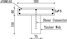
The timber-concrete “T” beams, of span 1.10 m between supports, were constituted of the web in pine timber (7.5 cm × 15 cm) and the cross-section of the flange in concrete (30 cm × 6 cm). The steel-concrete beam, of the same span and flange, was prepared by replacing the timber web with standard steel I-beam web (IPE 100). The longitudinal reinforcement of the flange for all specimens was five 8 mm diameter bars while the stirrups were 6 mm diameter bars every 140 mm. Typical cross section of test beams is shown in Fig. 1.
 Fig. 1. Typical cross-section of test beams.
The designed slump of concrete used for the flange was 50 mm. Test cubes were cured in water before testing at the ages of 7 and 28 days. The average compressive strength of the tested cubes after 28 days was 29 MPa. The study was fulfilled through three stages as follows:
Stage I: Three beams were prepared for this stage to study the efficiency of three different compositions of the timber web, namely, vertical glulam, horizontal glulam and massive timber. Hooked steel stud was implemented in this stage as a shear connector at intervals of 10 cm along the span of the beam. The details of beams used in this stage are shown in Fig. 2.
 Fig. 2. Details of test beams in stage I.
Stage II: As an output of stage I, vertical glulam web was chosen for completing other stages of the study. The parameters of study in this stage included the type of shear connector as well as encasing the timber web with either discrete or continuous FRP laminates. The shear connectors investigated were hooked steel stud, steel mesh and interlocking dovetail. The timber web was wrapped with three layers of U-shape FRP fabrics. Discrete and continuous wrapping were adopted for the timber web for each shear connector. The details of beams used in this stage are shown in Fig. 3 that includes a cutout view for the steel mesh shear connector.
 Fig. 3. Details of test beams in stage II.
Stage III: Post-stressing of the timber web in the longitudinal direction by means of mechanical torque using 16 mm bars with nuts was applied on two beams, one with vertical glulam web and another with massive timber web. Hooked steel stud was the shear connector used. Additional third beam was prepared to evaluate the cost-saving aspect of using timber-concrete composite beams. In this beam, standard steel beam IPE 100 replaced the timber web and hooked steel dowels of diameter 12 mm was welded to the upper flange of the I-beam. The details of beams used in this stage are shown in Fig. 4.
 Fig. 4. Details of test beams in stage III.
3.3. Testing
The beams are tested using the third point load over a simply supported span with length of 1100 mm. The load was applied gradually till failure. During the loading, observations and measurements included: crack pattern; strain in the longitudinal direction on the surface of the concrete flange and the timber web; central deflection, and the failure modes. Longitudinal deformations were measured using micro-measurement electrical resistance gages designed for bonding to concrete while dial gages of sensitivity 0.002 mm were used for recording the central deflection. Dial gages were also installed on the concrete top surface directly over the supports to record any settlement of the supports during testing. Fig. 5 shows the test set up featuring one of the test specimens ready for attaching the instrumentation and applying the load.
 Fig. 5. Test set up for beams.
4. Results and discussion
The results of the experimental program are presented and discussed in this section. The load-strain curves for test columns are shown in Fig. 6, Fig. 7, Fig. 8and the ultimate carrying capacity is shown in Fig. 9.
 Fig. 6. Load-deflection curves for test beams in stage I.
 Fig. 7. Load-deflection curves for test beams in stage II.
 Fig. 8. Load-deflection curves for test beams in stage III.
 Fig. 9. Failure mode of concrete-steel composite beam.
Fig. 6 illustrates the load-deflection curves for the three test specimens investigated in stage I. It is shown from the graph that the vertical glulam web imparts the test specimen the higher stiffness and load carrying capacity and the larger toughness compared to both horizontal glulam web and massive block web. The dis-continuounity of natural defects of wood specially cracks and knots in vertical glulam web minimized the weakness points in the web and improved the overall performance of the beam compared to that made of massive piece of wood. Moreover, the strong adhesive used to bind vertical laminates of timber through two continuous planes along the entire span of the beam provided additional reinforcing elements to resist tensile stresses and shear transfer. The recorded failure loads for the test specimens were 7.2, 6.5 and 6.4 tons for vertical glulam, horizontal glulam and massive block webs, respectively. The holes executed through the horizontal layers of adhesives in horizontal glulam web to fasten the shear connectors limited the functional efficiency of these reinforcing layers. Besides, the shear stresses transferred through horizontal planes of adhesive contributed in limiting the load carrying capacity of horizontal glulam.
Fig. 7 shows the load-deflection curves for the test specimens for stage II proposed to study the effect of type of shear connector as well as the role of FRP wrapping. The almost linear performance of the two beams enhanced with steel mesh shear connector supported the observation of shear failure at the interface between the concrete and the shear connector. The slip at the concrete-steel mesh interface led to partial composite action between concrete and timber and to increased bending deflections. Neither the FRP layers wrapping the full section of the timber web nor the concrete flange in compression zone boosted the load carrying capacity of the two beams because of this shape of failure. Concisely, beams manufactured using steel mesh shear connector showed marginal decrease in load carrying capacity and stiffness compared to other beams made with dovetail or hooked steel shear connectors.
On the other hand, beams provided with enhanced dovetail shear connector exhibited superior behavior in flexure in view of load carrying capacity, stiffness, toughness and ductility. This conclusion was verified in an experimental study on notched wood-concrete composite beams [16]. The attribution of this enhanced performance is a result of different reasons. First is the transfer of the shear forces between the timber and concrete over as large an area as possible. Other reasons include the swelling of timber when the moist concrete is cast in addition to grasping the timber with the shrinking concrete. The element responsible for the enhanced ductility of these beams was the steel dowels provided at the centers of the dovetail grooves.
The performance of beams made with hooked steel shear connectors was intermediate between those of dovetail and steel mesh shear connectors. The relative small area of timber acting to restrain the shear dowel and the concentrated loads that result limited the capability of hooked steel shear connectors of obtaining full composite action and developing the shear transfer seen with dovetail connectors.
Generally, wrapping the timber web with FRP laminates increases the structural stiffness of the beam and thus results in a smaller deflection at all load levels (complying with [19]. It was obvious that continuous wrapping along the whole span of the beam increased the resistance to shear flow and minimized the tendency to generate stress concentrations at transition zones as in the case of dis-continuous FRP wraps. The continuous FRP wraps in beams with steel mesh shear connector limited the slippage between the shear connector and the timber web and hence exhibited a marginal improvement in performance over dis-continuous ones.