Keywords
Introduction
Software-defined Networking (SDN) transforms networking from a closed embedded firmware into an open programmable software platform. It separates the data plane from the control plane and moves network control and management to a central controller (CC). The CC is informed of the network status, based on which networking decisions are optimized and reported to networking devices. This enables intelligence in major networking functionalities such as switching, routing, load balancing, traffic engineering, and network security. Particularly, the computational capabilities of the CC, the availability of the network status-related measurements at the CC, and the controllability of the network devices facilitate the development of intelligent applications at the CC to optimize the network performance.
The way an SDN is structured in a way like a computer operating system (COS). The operating system has a central kernel that interfaces between the hardware and software. The COS has “south-bound” components that manage the Central Processing Unit (CPU), memory, and networking, and “north-bound” components, which are referred to as the application layer that include general purpose applications. The SDN has a central component referred to as the network operating system (NOS) communicating between forwarding devices on the south-side, e.g., routers and switches, and network applications on the north-side [1].
The forwarding devices receive packets and process them by implementing actions commanded by the CC. These actions include dropping packets, modifying their headers, and sending them through one or more ports. The north-side applications are general-purpose applications and can have a variety of uses. Generally, their main functionality is to decide how packets are handled, but their functionality can easily become complex by implementing machine learning applications that can be used to optimize certain aspects of the network [1].
Benefits of SDN networks include but are not limited to, increased control over the network, increased speeds, customizable infrastructure, and increased security. SDN is a crucial component of current cloud services, which are more popular than ever. They allow data to be communicated easily through distributed systems, with high workloads being transmitted at high speeds across the network. This can be accomplished using network functions virtualization (NFV), which allows a virtual network to be divided into sections, thus, SDN's are highly scalable [2].
While traditional networking is hardware-oriented, the SDN approach is software-oriented, and that is what makes it superior since software can be easily programmed to perform tasks that would otherwise seem impossible through hardware programming. Because SDN has a CC, this allows network administrators to configure, manage, and expand their network, remotely from a centralized interface [2].
There are multiple SDN controller implementations but the most commonly used are OpenDayLight, POX, Ryu, and ONOS. All of them are open-source controllers; however, they differ in the programming language, the Graphical user interface, platform support, and performance. OpenDayLight (ODL) is written using JAVA and it is supported on Linux, Windows, and MacOS operating systems. It provides a command line interface in addition to a web-based Graphical User Interface (GUI). The disadvantage of ODL is that it is not easy to learn and program applications on it. POX controller is programmed using Python. It is supported on Linux but it can work on Windows and MacOS using virtualization; however, some features are only available in Linux. It provides a command line interface in addition to web-based (GUI). Programming applications for POX is easy and takes less time compared to Java-based controllers. The disadvantage of this controller is the poor network performance compared to other controllers [3]. The third controller is Ryu which is also programmed using Python. Ryu is only supported on Linux OS. It only provides a command line interface. It has the same disadvantage as POX because they are both implemented using Python [3], [4].
The controller that will be used in testing in this tutorial is the Open Network Operating System (ONOS). ONOS is an SDN controller based on the Java programming language and is designed in a way analogous to operating systems that are developed in Java as well, such as the Android operating system, providing API abstractions and resource allocation. It provides high network performance compared to the previous one, however, it is not easy to program applications for it. ONOS is what is referred to as an Open SDN controller, which uses a protocol called OpenFlow [2] to control the data plane level behavior of virtual and physical switches.
In traditional networking, routers, and switches perform both packet-forwarding, as well as high-level routing. However, in software-defined, ONOS instructs SDN-networking devices how to handle traffic. The means that the SDN and the switches communicate through is by using a protocol called OpenFlow. Switches that have the capability to use the OpenFlow protocol are called OpenFlow virtual switches (OVS) [1].
In the rest of this paper, we present a detailed tutorial on how to set up a software-defined network in Mininet, that is controlled by the ONOS CC. The Emulation environment facilitates testing the performance of applications implemented on ONOS. These applications can be implemented in Java at the CC to control a network topology modeled in Mininet using Python.
Prerequisites
To be able to follow along the tutorial, we recommend that the reader have a solid understanding of programming concepts especially object-oriented programming. To be able to use Mininet, we recommend that the reader at least know the basic syntax of Python. Knowing a Java build tool like Gradle or Maven will certainly make working with ONOS setup easier. A strong foundation in Linux is a must since all practical work will be performed in a Linux environment. Although not necessary, basic knowledge of the git software will prove useful. Finally, having a strong grasp over the concepts of computer networking is mandatory.
Emulation environment setup
There are multiple tools that need to be downloaded to be able to follow along with this tutorial. To be able to use Mininet or ONOS, a Linux environment needs to be set up. This can be accomplished in many ways, the first is to have a bare metal Linux OS distribution installed on your hardware, or, if you have a Mac or Windows device, you could download VirtualBox, which allows you to set up and manage virtual machines easily.
The Linux distribution we opt for is Ubuntu, with any LTS version 18.04 or higher. The optical disk ISO image required can be downloaded from their official website under the downloads section for desktop devices [5].
Next, a new Ubuntu virtual machine is created using VirtualBox and the settings are left as defaults. We recommend setting at least 10 GB for the hard drive file, 4096 MB for the RAM, 2–4 processors, 128 MB for video memory, and enabling the shared clipboard and drag-drop from host features. Then attach the downloaded ISO image file to the virtual machine from the devices section in the settings [6].
Now the virtual machine is ready for use and can be powered up successfully. Go through the installation settings, use preferences along the way, and create a user account. Note that the user account created during the installation process will be used for administrative operations, so wherever a “sudo” command is performed, the password of that user will be used to execute the command. The first step before using the machine is to ensure that all the packages are up to date, so the following command can be run.
sudo apt update && sudo apt upgrade.
Next, download git, which is a version control software that will facilitate downloading Mininet and ONOS, since both are open-source and they have their source code hosted on Github [7], [8]. The following command is required to download git and set its path in our global environment variable list.
sudo apt install git.
Downloading mininet and ONOS
Now use git to download Mininet which is accomplished in a series of steps as follows. First, clone the Mininet repository from Github.
git clone git:// github. com / mininet/ mininet.
Replace git protocol with https in case of git's failure.
git clone https:// github. com / mininet/ mininet.
Second, update git branch to the latest stable beta version of Mininet. Note that other versions other than “2.3.0b3″ can be used.
git checkout -b 2.3.0 b3.
Third, install Mininet from the repository that was just cloned to our device.
inatall. sh -a.
Note that the installed bash file is in the “util” directory of the downloaded repository, so either change the directory to it, or specify its full path or a relative path to it. At this stage, Mininet would be successfully installed [9]. To ensure Mininet is working properly, run the following command:
sudo mn.
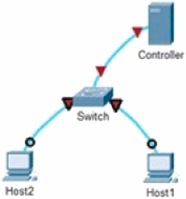
This runs a predefined network configuration sample that should produce an output with 1 controller, 1 switch, 2 hosts, and 2 links connecting each host to the switch as shown in Fig. 1. Furthermore, the terminal output should look like the output in Fig. 2. The command should execute in an average of 3 s
 Fig. 1
 Fig. 2
Note that Mininet could not be installed correctly or there might be some missing components if either message such as “Error setting resource limits” or “Mininet's performance may be affected” appear, the output takes a long time to appear, or the output does not appear at all. Usually, stack overflow will be very useful, but unfortunately, there are not many resources out there for Mininet and even fewer for ONOS. The most reliable resources are the software's respective documentation [10], [11].
So far the Mininet has been set up successfully, next, ONOS should be set up as well. The first step is to install some packages that are necessary for the ONOS installation. The command to install the packages is as follows:
sudo apt install ssh curl zip unzip python3 bzip2 pkg - config g++ zlib1g - dev Then, install Bazel, which is a build. To do so use the wget command which is a Linux command to download the file: wget https:// github. com / bazelbuild / bazelisk / releases/ download / v1.4.0/ bazelisk - linux - amd64.
Once Bazel has been downloaded, give it executable permissions using the following command:
chmod + x bazelisk - linux - amd64.
Then, move it to the binary directory as follows:
sudo mv bazelisk - linux - amd64 / usr/ local/ bin / bazel.
To verify that it has been successfully installed, running the following command should display the installed version.
bazel version.
To clone the ONOS repository, run the command:
git clone https:// github. com / opennet workinglab / onos.
Just like many Java APIs and SDKs, ONOS requires a root path to be set:
export ONOS_ ROOT =∼/ onos.
Followed by.
source $ ONOS_ ROOT / tools / dev / bash_ profile.
Building ONOS is just like building any Java project, except that bazel should be used. Running this command.
bazel build onos.
builds ONOS in the directory ONOS_ROOT 1.
At this stage, ONOS would have been installed, and it can be accessed from the terminal or the web browser UI. In the terminal, run one of the following two commands to launch an ONOS shell session on the localhost with IP address 127.0.0.1.
bazel run onos - local - clean debug.
or.
onos localhost.
Alternatively, it is possible to browser and visit localhost: 8181/onos/ui/#/device, which will activate the web UI session. The shell session gives more control over the web UI. If prompted to log in at any point, the credentials are “onos” for the username and “rocks” for the password [12].
Mininet and ONOS walkthrough
Mininet is an efficient Network emulating and testing tool. This provides advantages over the use of prototype hardware to design and test network applications. By emulating a virtual network, it is possible to configure different topologies and devices and test their connectivity as well as performance. Mininet's command line interface (CLI) allows us to use predefined network topologies or create custom ones with the help of Python scripts, which will be discussed in this section.
Note that to run Mininet using the “mn” command, it must be proceeded by the “sudo” command. The procedure of using Mininet's CLI goes through multiple steps. The first step is to define the topology, the default example which was discussed earlier contained 1 controller, 1 switch, and 2 hosts. We will first present the basic commands that can be executed on this simple network configuration.
Initially, type the following command in the terminal:
sudo mn.
This starts Mininet with the default network configuration. Standard Linux network commands can be used now to display information about the network. For example,
ifconfig,
which stands for “interface configuration” displays several settings of the modeled network, including ipv4 and ipv6,
MAC, and physical addresses. The “help” command.
help.
shows briefly Mininet's documentation file, which contains a list of the basic commands that can be used and some of their use cases. The command “nodes”.
nodes.
displays a list of names of all nodes in our virtual network, which includes controllers, switches, hosts, and any other devices that were defined. In the default example, the output should be “h1 h2 c0 s1″ [13].
1Note that a change of directory may be required using: “cd $ONOS_ROOT”.
The command “dump” is like “nodes”; however, it provides more details about each device such as the ipv4 addresses of their interfaces. The command.
net.
shows the links between the devices such as a link between the zeroth ethernet port of host 1 to the first ethernet port of switch 1, etc. We can see all three commands outputs in Fig. 3.
 Fig. 3
The ping command can be performed between devices. For example, this command will perform a ping from host h1 to host h2.
h1 ping h2.
This is mainly used to check connectivity between two hosts. By default, 4 Internet Control Message Protocol (ICMP) packets are sent from host 1 to host 2; however, the number of ICMP packets can be specified using the âĂIJ-câĂİ argument. For instance,
h1 ping -c 8 h2.
which sends 8 packets from host 1 to host 2. By using the “iperf” and “iperfudp” commands, a list of bandwidths for all links is displayed, the former command uses TCP, while the latter command uses UDP [13].
To exit the Mininet's CLI, just type “exit”. It is also a good practice to execute the command.
sudo mn -c.
which performs a cleanup for the Mininet environment. This is useful since it removes any temp files that have been created and frees any resources that were occupied.
So far, we have been using the default example topology and network configuration. The topology used is called “single” since it consists of only one switch. Other topologies can be created as well. First, to connect more hosts with a single switch, the following command is used:
sudo mn -- topo single,4.
This is basically the same configuration as the default one but with 4 hosts instead of 2. The topology is shown in Fig. 4-(a). Alternatively, the linear topology contains an equal number of switches and hosts where each host is connected to a switch, and each two adjacent switches are linked together. The linear topology can be emulated as follows,
 Fig. 4
sudo mn -- topo = linear,4.
Note that the number 4 is variable which can be substituted with the required number of switches. The emulated topology is shown in Fig. 4-(b).
The tree topology contains a tree of switches between the hosts and the controller, where the root switch is connected to the controller and each leaf switch is connected to a host. This can be accomplished in Mininet using the command.
sudo mn -- topo = tree, depth = 2, fanout = 4.
where the depth argument is the height of the tree and the fanout argument specifies the number of children each switch has. The output is shown in Fig. 4-(c) [14].
Although the built-in Mininet topologies are comprehensive, they do not cover all scenarios. Therefore, it is essential to make custom topologies and implement them in Mininet. Non-standard topologies can be implemented using Python script.
In the following discussion, a topology modulation will be shown in Fig. 5. The code in the script is organized into three sections, imports, class, and dictionary.
-
•
Import: import the topology class as follows “from mininet.topo import Topo”.
-
•
Class: create a class for our topology called “OurTopo”, which will inherit the imported class “Topo”. Our code fits inside the class constructor “init” and consist of four parts. First, calling the super constructor; second, defining our hosts; third, defining switches; fourth, adding the links.
 Fig. 5
It is critical to follow Mininet's convention of naming hosts and switches, where hosts start with a lower-case “h” followed by an integer, and switches start with a lower-case “s” followed by an integer [15].
The final part of our script models a tree topology and contains a key and a value. The key is the name of our topology, and the value is a lambda function that calls the class constructor for the specified topology. Note that multiple topologies can be established in the same script by creating a class for each topology and appending it as a key-value pair in the dictionary. Also, note that the key name of each topology will be used in Mininet CLI to emulate that topology as shown below.

Listing 1: Code that creates toplogy in Fig. 5.
Note that Mininet automatically connects all switches to the controller even without using “addLink” command. By default, all switches are connected to the controller. To launch the emulated topology in the Mininet CLI, use the command:
sudo mn -- custom script. py -- topo OurTopo.
where “script.py” is the path to the Python script, and “OurTopo”, is the key name of the topology from the dictionary in the Python script.
We can also test real network topologies such as the Abilene network shown in Fig. 6. The Abilene topology is commonly used in the research area. It consists of 11 connected nodes that represent multiple cities across the US. The following script shows how to implement the Abilene network in Mininet.


Fig. 6. Abilene topology.
Source: Adapted from [16].Listing 2: Code that creates Abilene topology. Source: Adapted from [17].
So far, implicitly, we have been using a default controller used by Mininet. Alternatively, we can explicitly use a specific version of the OpenFlow protocol by modifying the run command used earlier to become.
The open virtual switch (OVS) is a switch that uses the OpenFlow protocol, and “ref” is the reference OpenFlow protocol defaulted to by Mininet [15].
To replace the SDN controller with ONOS, for instance, first, open a terminal and execute the command:
Second, in another terminal, run an ONOS shell session:
Now, let Mininet refer to ONOS as the new controller. This is done by modifying the Mininet run command to the following:
By applying this set of commands, Mininet is successfully set up to use ONOS as the controller.
“help onos” is one of the useful commands, which will display a list of commands that can be used and a brief explanation on how to use them. To get detailed documentation for a specific command, you can type it and succeed it with “–help”. Another useful command is “devices”, which lists the devices connected to ONOS and some of their properties like their id in hexadecimal, status, type, etc. The list contains 15 properties, shown in Fig. 7, but only part of it will be displayed for space limitations [12].
 Fig. 7
The “links” command displays a list of links in the topology connecting the SDN devices, stating sources and destinations [12].
In Fig. 8, the source and destination fields are displayed in a device/port pair format. The “hosts” command displays details about the hosts that are currently in the system as shown in Fig. 9 [12].
 Fig. 8
 Fig. 9
To be able to use networking commands that generate traffic, like “ping” or “traceroute”, or if one is interested in using other software that generates traffic, we need first to activate the forwarding application that is part of ONOS. The forwarding application is what helps ONOS to decide how flow routing is handled. When pinging one device from another without activating the forwarding application, an error message is displayed, i.e., “Destination Host Unreachable”, just like in Fig. 10 where a sample is displayed.