1. Introduction
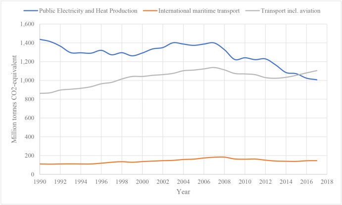
One of the aspects of climate change is global warming which is associated with the rise of the Earth's temperatures. It occurs when carbon dioxide (CO2) and other air pollutants absorb sunlight and solar radiation in the atmosphere for a long term, trap the heat and make the Earth get hotter (NASA, 2018). In 2018, the Intergovernmental Panel on Climate Change (IPCC) reported an increase in temperature of 1.5 °C (IPCC, 2005). Therefore, emission reduction in all modes of transport is necessary to reduce greenhouse gas (GHG). Fig. 1 shows the GHG emissions from different sources of power till 2017, while Fig. 2 presents the change level in GHG for each sector. Both figures show that further action is required to cut emissions, particularly in road transport, the largest contributor to transport emissions, as well as the other sectors by 2050.
 Fig. 1. Greenhouse gas emissions from different power sources in the EU (EEA, 2021).
 Fig. 2. Change in GHG emission levels from transport in the EU from 1990 till 2018 (EEA, 2021).
Regarding the shipping industry, which is the focus of this review paper, and according to the International Maritime Organization (IMO), 90% of world trade is carried by sea to support the import and export of goods and thus sustains the modern world. It has been reported that the total number of ships in the world fleet increased in 2019 by 35% compared to 2015 and by 51.5% compared to 2010 (Equasis, 2019). This large number of existing ships forced the IMO, which is mainly concerned with maritime safety, to adopt, through the Marine Environment Protection Committee (MEPC), a wide range of measures to control the shipping industry's pollution in support of the global action towards climate change mitigation, even though shipping is the least environmentally damaging mode of transport compared to the other modes of transportation, as shown in Fig. 1 (IMO, 2016b, 2019b).
From this point, the "green shipping" or "sustainable shipping" concept was applied to the shipping industry to transport goods using the lowest possible energy or, in other words, the seagoing ship that contributes to improving the current environmental condition. The presented stringent regulations and policies inspired researchers worldwide to think about new ideas and improve the existing ones. Reaching the required level of green shipping is a challenging way that has significant upgrades in the different technologies proposed every year; each one has its impact on the industry to reduce GHG (Bouman et al., 2017), where there are many research projects have been funded to investigate the impact of ideas on the decarbonization of the maritime sector (Mallouppas and Yfantis, 2021). Several research areas have been considered for the concept of green shipping (EMEC, 2010), while this paper focuses on the main topics that directly affect ship performance, fuel consumption and exhaust emissions. Combining the comprehensive review with the concept of bibliometric analysis (Romano and Yang, 2021) extends the previous research works and aims to contribute in detail by providing.
-
•
a broad overview of what has been done in the last years, from 2010 till 2022 and in particular in the last four years, where there are big achievements in these last years from the different stakeholders to reduce the impact of shipping on the environment. This study contributes by describing the new technologies, techniques, decision support methods (i.e. research operation) and software, that have been suggested and are under improvement, already developed and used to achieve the required decarbonization level and green shipping concept and the percentage of emissions reduction for each technique,
-
•
a bibliometric analysis, showing the interest of the researchers towards improving the ship performance and the number of papers published in each technique and their citation patterns,
-
•
a review of the papers to extract the main findings related to decarbonization and green shipping and to identify the emerging trends and future research needs.
This raises the following questions.
-
•
What progress has occurred in each topic toward green shipping, decarbonization, and sustainability, especially in recent years?
-
•
How is each technique's performance calculated and what is the effect on green shipping, decarbonization and sustainability and their relations?
The remainder of this paper is organized as follows. Section 2 presents the role of MEPC in the maritime industry to control environmental harm. Five main topics have been presented in detail from sections 3 to 7, each with its technologies, covering the development of ship design, alternative fuel and operational conditions. A bibliometric analysis of the full set of papers considered in this paper is provided in section 8. Finally, a discussion and the main findings from the performed literature review, and a presentation of the development trend are presented in section 9 followed by a conclusion presented in section 10.
2. Role of MEPC in the maritime industry
MEPC is the IMO's technical body that is concerned with marine pollution and addresses environmental issues and other related matters. Since the last decade, its primary focus has been to propose important guidelines and to apply stringent regulations through indices that are proposed, applied and revised every session to significantly reduce GHG from ships and thus increase the fleet's energy efficiency in terms of design and operational points of view; it is presented in the annual/half annual sessions MEPC (IMO, 2019c). The GHG includes CO2, methane (CH4) and nitrous oxide (N2O) and is expressed in CO2e. These regulations are made with the adoption of amendments to the International Convention for the Prevention of Pollution from Ships (MARPOL) (IMO, 2019a).
According to the most recent IMO GHG study (IMO - MEPC, 2020), an increase of 9.6% in GHG was reported in 2018 compared with 2012. Therefore, a clear pathway is proposed, combining energy-saving technologies (Winkel et al., 2015), ship speed reduction (Elkafas and Shouman, 2021), and low-carbon fuel (El-Gohary et al., 2015) to reduce the carbon intensity by at least 40% by 2030 and the total annual GHG by at least 50% by 2050 compared to 2008. At the IMO MEPC 76, a short-term measure has been adopted that enters into force at the beginning of 2023, combining the Energy Efficiency Existing Ships Index (EEXI) and the Carbon Intensity Indicator (CII). The rating of CII from A to E as a ship rating mechanism has been proposed in MEPC 75, and the strengthening of the Ship Energy Efficiency Management Plan (SEEMP), especially in the late rank (D and E). This means that the first annual reporting will be at the end of 2023, and the first rating given will be in 2024. Reviewing the effectiveness of EEXI and CII will be required to develop further amendments. After the IMO MEPC 76, Psaraftis (2021) commented on the decision made at the meeting briefly as there is no clear measurement that can be used in general to evaluate the energy efficiency of the ships. There are two ways, Annual Efficiency Ratio (AER) and Energy Efficiency Operational Indicator (EEOI).
During the transition period till 2030, CII is necessary. There are also some unclear points related to collecting data to compute the EEOI, which will be very sensitive information to ship owners. It is also incompatible with the IMO Data Collection System (DCS). The Engine Power Limitation (EPL) technique can reduce EEXI, while it is unclear if it will be effective compared to decreasing the sailing speed. So, combining several metrics is essential to address the design and operational efficiency and thus provide a plan for system management during this energy transition period. This requires great cooperation between regulators and other stakeholders to cut GHG emissions from the maritime industry. However, it is important to balance several factors to reach the common goal of transitioning towards zero-emission smoothly (Lloyd's Register, 2021). These factors include society, compliance, competitiveness, and technology. In terms of society, the transition must be carefully handled not to affect the most vulnerable groups of citizens. In terms of compliance, it is important to achieve a real emission reduction as well as the international agendas not conflict with each other. Otherwise, a carbon tax price will be bought by the shipowners covering all emissions during ship trips with US$100 per tonne on bunker fuels as the initial cost (ECEEE, 2022) for those ships that sail in the European Union (EU). However, half of this cost is reduced to half for international voyages that start or end at EU ports. In terms of competitiveness, the standard sources of zero-carbon energy must be commercialized and viable to encourage and ensure widespread adoption. In terms of technologies, short-term measures with low risk are welcomed as a rapid transition solution.
In addition to the GHG emissions reductions, annex VI in MARPOL sets limits on nitrogen oxide (NOx) and sulphur oxide (SOx) and particulate matter (PM) emissions (IMO, 2019a). Regarding the NOx emissions, Fig. 3 shows the limits of NOx emissions produced from diesel engines which are reduced by 80% in Tier 3 compared to the first tier under regulation 13 of MARPOL Annex VI. They are calculated as the total weighted emission of NO2 and determined using the relevant test cycles and measurement methods as specified in the NOx Technical Code (IMO, 2017). Each engine must comply with the limitations of the NOxtechnical code and be verified by an Engine International Air Pollution Prevention (EIAPP) Certificate. More details about the reduction methods of NOxemissions will be presented in section 5. Regarding the SOx and PM emissions, regulation 14 of MARPOL Annex VI presents the main requirements to control the level of sulphur in the fuel as shown in Fig. 4, which was reduced from 3.5% to 0.5% globally at the beginning of 2020.
 Fig. 3. NOx emissions limitations among the three tiers (DAIHATSU, 2021).
 Fig. 4. Amount of sulphur in marine fuels (DAIHATSU, 2021).
The concept of emission control areas (ECAs) has entered into force since 2006. Some sea areas have stringent controls of both NOx and SOx emissions to minimize these airborne emissions from ships, as defined by Annex VI. The list of the sea areas is updated each year, and the North and Baltic seas are the recent ones included, as shown in Table 1. The level of NOx emissions in these areas must not exceed the limits of Tier 3 as proposed by IMO, while the percentage of sulphur in the fuel does not exceed 0.1%.
Table 1. Amendments adopted to the MARPOL Annex VI: Air pollution in ECAs (IMO - MEPC, 2016).
| Emission Control Areas | Type of emissions | Amendments adopted to the MARPOL Annex | Entry into force of the amendments | More stringent measures in effect from |
|---|---|---|---|---|
| Baltic Sea | SOx | – | – | 19 May 2006 |
| NOx | 7 Jul 2017 (MEPC.286 (71)) | 1 Jan 2019 | 1 Jan 2021 | |
| North Sea | SOx | 22 Jul 2005 (MEPC.132 (53)) | 22 Nov 2006 | 22 Nov 2007 |
| NOx | 7 Jul 2017 (MEPC.286 (71)) | 1 Jan 2019 | 1 Jan 2021 | |
| North America | SOx and PM | 26 Mar 2010 (MEPC.190 (60)) | 1 Aug 2011 | 1 Aug 2012 |
| NOx | 26 Mar 2010 (MEPC.190 (60)) | 1 Aug 2011 | 1 Jan 2016 | |
| United States Caribbean Sea | SOx and PM | 15 Jul 2011 (MEPC.202 (62)) | 1 Jan 2013 | 1 Jan 2014 |
| NOx | 15 Jul 2011 (MEPC.202 (62)) | 1 Jan 2013 | 1 Jan 2016 |
From that point and to evaluate the level of emissions from ships, the international regulators have proposed several energy-efficiency measures to improve the ships' energy efficiency and drive toward ship decarbonization. The main target of these measures, which are continually evaluated over the years (Bergholtz, 2013; Figari et al., 2012; Winkel et al., 2015), is to present a relation between the level of exhaust emissions from the main and auxiliary power systems compared to the cargo hold volume and travelled distance.
The Energy Efficiency Design Index (EEDI) is an index formulated for new ships at the design stage to cut down the amount of emissions from these ships. DNV (2018a) has developed a tool to compute the EEDI for the whole fleet. The EEDI is expressed in grams of CO2 per tonne-mile or in other words, the ratio of environmental cost to the benefit for society. Each type of ship has its limits proposed. However, the values of these limits will be reduced by 30% by 2025 compared to the zero phases in 2013 (Puisa, 2015), as shown in Fig. 5; therefore, different technologies are required to significantly reduce the EEDI limits (El-Gohary, 2013; Palomares, 2011; Papanikolaou et al., 2011).
 Fig. 5. Phases for reduction factors of EEDI (Puisa, 2015).
The Ship Energy Efficiency Management Plan (SEEMP) is another operational measure that establishes a cost-effective mechanism to improve the ship's energy efficiency (IMO, 2016a). It is based on four steps; planning, implementation, monitoring, and evaluation and improvement. Firstly, it is important to define the current status of energy consumption and how it can be reduced. Secondly, implementing the methods is the responsibility of the involved stakeholders, then monitoring the effectiveness of the implemented SEEMP. Finally, it is necessary to evaluate the previous stage's results to check the effectiveness of the applied SEEMP to improve the suggested plan. It is applied to new and existing ships to manage ship and fleet efficiency performance over time, based on the EEOI as a monitoring tool. This operational measure can optimize and improve voyage planning, introduce the timing of ship hull cleaning, and suggest installing new types of equipment onboard(Tikka, 2011).
The Energy Efficiency Operational Indicator (EEOI) is considered a monitoring tool to serve the decision in SEEMP (IMO, 2009). It is used to monitor and identify the operation and personnel performance as well as the quality control procedures. It aims to provide a transparent and recognized approach to assessing the level of GHG emissions from the ships in their real operating condition along the route. Tran (2017) developed an open tool to support the computation of the EEOI for different types of ships based on the fuel type, the amount of cargo carried, the distance of the voyage and the sailing speed. For an accurate estimate of EEOI, real data is important to be provided by the fleet to take the right action (Perera et al., 2015). Some studies presented the effect of external forces on the ship and engine performance, such as biofouling, which can reduce the propeller performance by 30% (Owen et al., 2018).
The Energy Efficiency Existing Ship index (EEXI) will enter into force on the 1stof January 2023 and applies to all vessels above 400 gross tonnage (GT) falling under MARPOL Annex VI. The EEXI is a one-time certification targeting design parameters. The calculation guidelines refer to the corresponding EEDI guideline for new buildings. Most of the guidelines have been finalized at MEPC 76, while some are still not, according to (DNV, 2019).
From 2023, the Carbon Intensity Indicator (CII) requirements will take effect for all cargo, RoPax and cruise vessels above 5,000 GT and trading internationally. The CII addresses the actual emissions in operation by measuring how efficiently a ship transports goods or passengers and is given in grams of CO2emitted per cargo-carrying capacity and nautical mile. Then, the ship is given an annual rating ranging from A to E, whereby the rating thresholds will become increasingly stringent towards 2030. If the ship fails to comply with the CII limitations, she will be asked to revise before returning to service (Qi et al., 2021). Therefore, according to Wang et al. (2021e), it is essential to define the potential versions of CII based on more elaborate models and real data, to ensure the effectiveness of each version and the ability to improve a new CII.
The Environmental Ship Index (ESI) was developed by World Ports Climate Initiative (WPCI) to make up for the deficiency of the previous indicators, such as EEDI, which deals only with partial problems. This index aims to identify seagoing ships with better performance in emission reduction by presenting a unique measure of the entire power system from both sides: energy efficiency and environmental impact without any specific restrictions (Ančić et al., 2018; WPSP, 2019). This index evaluates the main three types of exhaust emissions simultaneously; CO2, NOx and SOx which are implemented in one equation plus some additional points related to the power supply from shore. Mocerino and Rizzuto (2020) estimated the ESI index for several cruise ships, where the results show future suitability for ports and suppliers.
While there is a big interest from the regulators to reduce the GHG from ships as it is related directly to the ship hull and engines, covering the ballast watermanagement systems (BWMS) is an important topic to be considered when the green shipping is discussed. The Ballast Water Management (BWM) Convention is a treaty adopted in 2004 by the IMO to prevent the spread of potentially harmful aquatic organisms and pathogens in ships' ballast water. From 8 September 2017, ships must manage their ballast water so that aquatic organisms and pathogens are removed or rendered harmless before it is released into a new location. Ships have to carry BWM plan, ballast water record book and International BWM Certificate. There are two ballast water management standards (D-1 and D-2). The D-1 standard requires ships to exchange their ballast water in open seas, away from coastal areas, while the D-2 standard specifies the maximum amount of viable organisms allowed to be discharged, including specified indicator microbes harmful to human health and all ships must conform to at least the D-1 standard; and all new ships, to the D-2 standard. More details can be found in (MEPC.279 (70), 2016).
3. Hull design
This section presents the first main aspect towards the concept of a green and sustainable ship. Several papers have been presented and discussed related to three main categories in this section. The first one is the design and optimization of hull form to reduce ship resistance. The second one is the types of coating used to ensure a clean hull over a long period, and the third one is the different air lubrication technologies that are integrated into the ship hull with the required modifications. More details about each category are presented in the following subsections.
3.1. Hull optimization
The hull is a ship's watertight enclosure to satisfy a set of different types of requirements and to provide sufficient protection for the machinery, cargo, and passenger accommodations. The hull form is represented by a series of curves which are the intersections of the hull with three sets of mutually orthogonal planes. Optimizing the hull shape becomes an essential process to reduce the hull resistance and thus the power required (Yang and Huang, 2016); it is a main effective step to minimize the EEDI towards green shipping. The Scopus database identifies 473 papers that have been published in the defined period distributed, as shown in Fig. 6.
 Fig. 6. Distribution of hull optimization papers over the years.
Hull optimization requires the use of an operation research technique that operates over methods that quantify the hull resistance, either based on potential flow codes or Computational Fluid Dynamics (CFD), which has become more popular recently (Gil Rosa et al., 2021; Islam and Guedes Soares, 2019a, 2019b; Labanti et al., 2016).
Using a single objective optimization model, Kim and Yang (2010) used two approaches, radial basis function interpolation and the sectional area curve of the hull, to optimize the initial hull of the KRISO container ship (KCS) and evaluated by the defined fitness function. Based on this model, the total drag has been reduced compared to the reference hull. He et al. (2011) extended the previous work by applying a multidisciplinary design optimization and considering manoeuvring, seakeeping and resistance to achieve an optimum design. A genetic algorithm (GA) has been used by Le and Kim (2011) to generate a single non-uniform B-spline (NUB) surface. This technique can be used during the preliminary stage of ship design to provide surfaces with high efficiency for better visualization and to be used in finite-element methods.
A multi-objective genetic algorithm (MOGA) has been applied to optimize a fishing vessel by considering the ship's resistance, seakeeping, and stability (Gammon, 2011). The results have been compared to an existing hull, where the ship's performance has been improved. During computational fluid dynamics (CFD) computation, response surface methodology (RSM) is considered to optimize the hull form while reducing the wave drag (Kim et al., 2011). The same concept was applied later by (Liu et al., 2018) based on a surrogate modelto optimize the KCS hull form at full speed. At the same time, Feng et al. (2018)used support vector regression (SVR)-based surrogate models to improve the resistance and wake field of an offshore aquaculture vessel hull form. This technique has the benefit of reducing the computational cost associated with the CFD runs. Diez and Peri (2012) optimized the hull form by addressing the epistemic uncertainty of the location of the centre of gravity. Based on the hydrodynamic performance, Han et al. (2012) and Krivoshapko (2022)developed an optimization model that can be able to generate new types of hull forms. This model was used to reduce the resistance of a large container ship to operate at high speed. The hull form of a ship trawler has been improved during trawling conditions to achieve the best performance of the ship (Zhao et al., 2021a). The concept of Multi-fidelity Co-Kriging surrogate model has been presented by Liu et al. (2022b) showing the ability to achieve high accurate results in terms of efficiency than the previous methods and the final optimization results can be guaranteed.
In (Mahmood and Huang, 2012), the geometry of the bulbous bow has been optimized by analysing the fluid flow using the CFD model to reduce the resistance. In (Matulja and Dejhalla, 2013), the hull form, including the bulbous bow, has been optimized by minimizing the wave resistance, while Li et al. (2014) optimized the bow and stern shape, achieving a 5% reduction in resistance and improving the wake field. Furthermore, the optimization procedures have been performed to find the optimal bow shape in different cases; the laden and ballast condition of a tanker ship (Legović and Dejhalla, 2015), a container ship in different operating conditions (Lu et al., 2016) and waves (Feng et al., 2021), the added resistance in case of KVLCC2 tanker (Bolbot and Papanikolaou, 2016), a fishing vessel coupling CFD and design of experiment (DoE) (Hong et al., 2017b) and strength assessment of the corner bracket connection (Silva-Campillo et al., 2022). By applying a combination of several machine learning methods (Mittendorf et al., 2022), the selection of a suitable hull operating from a dataset in weather conditions can be more accurate and faster (Islam et al., 2022) than using only CFD techniques.
The optimization model is extended to simulate different types of propellers of a liquified natural gas (LNG) ship, as in (Kim et al., 2014), where the authors confirmed a reduction in fuel consumption by 13% for twin-screw compared to single-screw. Furthermore, the wake field of a twin skeg container ship has been improved by optimizing the hull form-based CFD model, and the resistance has been reduced by around 9% (Chen et al., 2016). In addition, Čerka et al. (2017) compared different skeg geometries and studied the turbulence of water in front of the propeller, which gives a good idea for selecting the optimum skeg. Liu et al. (2022c) studied the interaction between ship resistance and wake field, showing that the hull lines have a dominant effect to reduce pressure resistance and improve the wake field. The same concept has been presented in (Nazemian and Ghadimi, 2021; Wu et al., 2022).
Scamardella and Piscopo (2014) presented an improvement in ship seakeeping parameters for a passenger ship compared to the reference hull while keeping constant the main dimensions of the hull and ship displacement. At the same time, the Gaussian distribution coupled with an optimizer shows its effectiveness in reducing ship resistance (Choi and Yoon, 2016). By considering the EEOI, Hou (2017) presented a hull form optimization design method based on uncertainty to find the optimal hull form during operation. The method is applied to different cases and shows its effectiveness for a hull design. Zha et al. (2021) adapted the optimization tool to improve the vertical motion performance in irregular head waves. Also, optimization methods are applied to enhance the deformed mesh quality of the numerical model during CFD computation (Jeong and Jeong, 2020).
In summary, CFD models have been used to improve ship performance with high accuracy. It depends on the specific part of the ship hull that needs to be optimized according to the study's objective. The objective can be technical parameters such as ship resistance, manoeuvring, seakeeping and stability or related to the hull form's mesh parameters. Based on several trials, the model results are exported and presented into a surrogate model, which is then coupled to an optimization model to compute the optimal design. Fig. 7 shows a schematic diagram of the CFD models and their interaction with the optimization procedures.
 Fig. 7. Schematic diagram of optimization procedures coupled to CFD models.
By analyzing the papers since 2019, the developed numerical models are focusing on including ship operation during the design stage by studying the ship's performance in different weather conditions to reach the optimum hull form that can ensure higher energy efficiency in safe conditions.
3.2. Ship coatings
The marine coatings are a barrier between the water and the hull to protect it from damage. The development of marine coatings is subjected to the standards issued by the International Paint and Printing Ink Council (IPPIC) to improve the performance and development of anti-fouling and anti-corrosion coatings used on the hull and inside the tanks. It has been found that around 193 papers have been published, and the distribution of the papers is presented in Fig. 8.
 Fig. 8. Distribution of ship coating papers over the years.
The accumulation of biofouling increases the ship's resistance and, thus, the power required and fuel consumption to achieve a certain ship speed (Campos et al., 2021; García et al., 2020). Also, it leads to rusting the hull and exposing the hull to damage. Therefore, cleaning the hull and high solvent coatings are essential for the ship's life to save power and fuel and avoid increased resistance due to hull deformation, even if it is clean (ITTC, 2008; Yusuf et al., 2022).
DNV (2017) provided full guidelines to protect the ship from corrosion as well as the type of painting for each hull material. Providing an effective inspection during the period in the dry dock is important to control the quality of the painting and save time for the ship inside the dry dock (Swain and Lund, 2016). It requires to have a piece of clear information about the vessel and its trip to improve the quality of the coatings according to each operating area. Robots have become an effective solution for cleaning hulls and removing the marine growth from both hulls and tanks (Restivo and Brune, 2016). The strains of the hull structure and the fracture strains of the aged coatings are simulated by Ringsberg (2017) using the finite element method to consult the owner to renew the coating protection to avoid corrosion, where the laser treatment can be used effectively to avoid any hull damage (Zimbelmann et al., 2022).
De Baere et al. (2013) provided an economic study comparing different solutions to reduce corrosion. The authors suggested that the use of durable TSCF25 coating and lifetime-lasting aluminium anodes are improving the concept of the actual basic tank. Heyer et al. (2013) provided an overview of the coating process and the corrosion problem inside the ship; they mentioned that the epoxy coatings as new materials would replace the coal tar epoxy coatings. Cao et al. (2020) approved that the grafting of Magainin II on the surface increases the surface's antibacterial performance. Kim et al. (2021b) used Tannin-FeIII (TA-FeIII) coating obtained from biomass as an alternative to typical phlorotannin, and they confirmed that it is eco-friendly, safe and cost-effective. Also, Bi et al. (2021) suggested the use of alginate hydrogel coating derived from biomass to protect the oil tanks. This type of coating has good environmental stability and acts toward a green oil spill control strategy. Zoolfakar et al. (2022) discussed the effect natural superhydrophobic materials mixed with paint based on different parameters, such as the thickness of paint and underwater depth, to determine the suitable raw material to be further used commercially.
In summary, the published papers concluded that selecting the coating materials is essential to ensure the cleanness and durability of the ship hull. Also, the recent studies since 2019 focusing on the use of green raw materials in the production of coatings, such as biomass, will have a significant positive effect on the environment as well as cost-effectiveness.
3.3. Air lubrication technologies
Air Lubrication is a technology developed to reduce resistance, especially frictional resistance, which accounts for more than 60% of total resistance (ITTC, 2017) between the ship's hull and seawater using air bubbles. According to the selected international database, 68 papers have been published from 2010 to 2022. Fig. 9 shows the distribution of the papers published concerning air lubrication technologies. A great interest in this topic has been noticed since 2018 due to the stringent regulations applied to present a way to improve air lubrication systems and achieve significant energy savings.
 Fig. 9. Distribution of air lubrication technologies papers over the years.
There are some technologies tested on full scale and are currently available in the market as follows.
3.3.1. Air lubrication system (ALS)
ALS provides a constant air bubble flow using blowers installed onboard to lubricate the flat bottom area of the hull, thus reducing resistance up to 6% (Giernalczyk and Kaminski, 2021), while minimal changes in ship structure are required. ALS is an Innovative Energy Efficiency Technology recognized by IMO under category B-1 according to the MEPC.1/Circ.815 (MEPC.1/Circ.815 17, 2013) as it has an effect on lowering the EEDI value. Several companies entered into the production of the ALS after the first launch by Silverstream company, such as Mitsubishi Company and Samsung Heavy Industries. This system requires comprehensive analyses and measurements to evaluate the performance of the complexity of the system. Therefore, CFD simulation is used to simulate the performance of the ship equipped with ALS (Sindagi et al., 2020), while an artificial neural network (ANN) can be considered to analyze the experimental data and find a correlation to optimize the system parts (Sindagi et al., 2021) as well as the ship hull (Cucinotta et al., 2017). It has been concluded that the performance of ALS depends on the ship's speed. It shows effectiveness in drag reduction at slow speeds than at higher speeds due to the increased sharing of the wave-making resistance.
3.3.2. Air cavity ships (ACS)
ACS or Air Chamber Energy Savings (ACES) is the second choice of air lubrication technique that uses a large compartment in the hull bottom to fill with air and isolate the hull bottom from water, thus reducing frictional resistance. This technique can maximize the cavity length and, at the same time, minimize the air supply (Slyozkin et al., 2014). ACS can achieve a drag reduction of up to 26%, especially at the highest flow speed and based on the created cavity area. By comparing the base hull with other modified hulls (Cucinotta et al., 2017), the height and position of the compartment affect the trim that must be avoided for air stability (Hao, 2019) as well as the sinkage of the hull as important parameters to be considered in addition to the resistance and power to ensure the safety and the performance of the ship, especially in transition mode once the air supply is shutting down (Fang et al., 2021). In (Butterworth et al., 2015), the authors ensured a 16% drag reduction, while the vertical motion responses of the hull are important to be noticed as they are affected by the air cavity. In (Matveev, 2022), the ACS demonstrates lower vertical accelerations in waves compared to the similar solid hull.
3.3.3. Winged air inject pipe (WAIP)
WAIP is another technique that uses air lubrication by generating ultra-fine microbubble generation, which can reduce power by up to 15%. Microbubble generation requires a very small amount of power, and the system is composed of a series of small air chambers fitted with a foil (Zhang et al., 2018). In (Yanuar et al., 2020; Yanuar. et al., 2020), the authors used CFD computation to find the optimal values of pipe diameter, chord length and the angle of attack of the hydrofoil. It has been found that the ship's performance can be increased by 10% by finding the optimal values of the parameters.
In summary, air lubrication technologies show a significant reduction in resistance, thus affecting the power and reducing the consumed fuel. Experimental results began to be collected based on the existing models and ships, while the CFD models have been widely used in the last four years due to the improvement of computer performance to predict an accurate performance of air lubrication systems. Based on the two types of data, experimental and numerical, the machine learning techniques effectively find the correlation between the system parameters for further optimization procedures.
4. Propulsion systems
This section presents the second main aspect towards the concept of a green and sustainable ship. In this section, several papers related to propulsion systems have been presented and discussed in the following subsections. This includes the development of engine technologies to minimize fuel consumption and ensure the combustion process using alternative fuels. Also, the design and selection of marine propellers are discussed to decide on a suitable propeller for a given ship. The selection of an efficient steering gear is presented to minimize power consumption and ensures smooth maneuvering. Finally, the use of different wind energy technologies is discussed as a clean type of marine systems.
4.1. Engine technologies
Whether four-stroke or two-stroke, the marine engine is an essential component of the ship as it is the main source of power and, at the same time, the primary source of pollution due to the burning of different types of fuel, so the energy can be converted to a mechanical force. Therefore, the importance of developing the different parts inside the engine is the main concern of the researchers to improve the engine performance and thus reduce exhaust emissions. 2,170 papers have been published in the defined range of years, as shown in Fig. 10, which indicates an increment in the last four years (2019–2022).
 Fig. 10. Distribution of engine technologies papers over the years.
Marine diesel engines have shown a great revolution these years towards decarbonization and reduction of fuel consumption to fit the market needs. The simulation software developed varying from 0D models to 3D models, is good support for the studies to support design changes. Several simulation software has shown a great interest in the market, namely, Aspentech (2019), supporting 0D models, Ricardo Wave Software (2019), Gamma Technologies LLC (2017) and AVL (2017), supporting 1D and 3D simulation, as well as Ansys (2018), OpenFoam (2018) and SoftInWay Inc. (2018) supporting 3D simulation, where the last one is mainly focusing on the modelling and simulation of turbomachinery. This software is mentioned as they are most common in the market in engine simulation. The software assists in the rapid development of engine performance as well as the reduction of exhaust emissions by optimizing the different parts of the engine.
The concept of a dual-fuel engine became widely used. Several engines have been upgraded to support the use of alternative fuel as the main fuel and the injection of a small quantity of diesel oil to begin the ignition (Benvenuto et al., 2017; Marques et al., 2019; Park et al., 2017). While this concept is not new, as developed by Karim (1980), the engines nowadays support this concept due to the lower exhaust emissions, which comply easily with tier 2 and can reach Tier 3 due to the availability of several new fuels (Liu et al., 2022a; Wu et al., 2023; Zhang et al., 2022).
The turbocharger's performance has been improved by increasing the pressure ratio and the amount of compressed air, which leads to an increase in the engine performance of about three times more than the naturally aspirated engine. Therefore, reducing the power-to-size ratio of the engine, reducing the amount of fuel consumption, cost reduction and ensuring flexible engine operations are easily achieved (Latarche, 2020). Four basic turbocharging arrangements have been proposed and studied, while the most commonly used in the large engine is the constant pressure method ensuring a higher degree of efficiency (Tadros et al., 2015). With the existing charger air cooler, the air's temperature is reduced, and the air's density is increased, thus improving engine performance and reducing exhaust emissions (Senčić et al., 2022; Tadros et al., 2020b). Two-stage turbocharging is a common concept presented in marine applications, allowing more air to be compressed with lower compression energy and higher efficiency for both compressor and turbine due to the lower specific loads. It can be used to increase the exhaust temperature by controlling the wastegate and thus increase the performance of SCR(Verschaeren and Verhelst, 2018).
With the existence of the two-stage air cooler and the Miller cycle (Cui et al., 2013; Wang et al., 2021c), the amount of air is controlled inside the cylinders, and the level of NOx emissions is reduced by 25%. Also, the Miller cycle greatly affects engine performance with the single stage of the turbocharger, as shown in (Tadros et al., 2019; Wei et al., 2019, 2022). The turbocharger cut-out and sequential turbocharging system provide a great engine performance for higher and lower loads, which has a direct effect on NOx emissions and keeps the engine under the limits of Tier 2 while reducing the fuel consumption by 3–5% than using the conventional turbocharging system (Sun et al., 2017; Zhu et al., 2020b).
It is essential to study the back pressure along the system (Güdden et al., 2021) to ensure the best performance along the engine load diagram, especially with high back pressure (Ma et al., 2022b) to be able to recover according to the thermodynamic properties of the engine in energy and exergy analysis (Ma et al., 2023). Sapra et al. (2017) found that the air-excess ratio, exhaust receiver and exhaust valve temperature are the main parameters against the formation of high back pressure. ABB (2019) takes the lead in developing several types of turbochargers covering a wide range of engine power, where the efficiency has been improved by 36% compared to 1970, while titanium has been used for higher loads instead of aluminium. The hybrid turbocharger (HTC), where the electric generator is coupled to the turbocharger shaft, can be used to improve both engine and SCR performance (Nielsen et al., 2020).
Exhaust gas recirculation (EGR) is another solution to reduce NOx emissions through different proposed configurations, such as low, high, and hybrid pressure loops. Combining the techniques mentioned before with EGR leads the engine to comply with the limitations of Tier 3 without any additional after-treatment system (Wang et al., 2021d; Zu et al., 2019), as it directly affects the combustion process, thus improving fuel economy. However, it is essential to optimize the rate of EGR to achieve the best engine performance (Stoumpos and Theotokatos, 2020) and, in particular, with the turbocharger operations (Lu et al., 2022). The EGR shows the most economical solution, either with or without the installation of after-treatment systems (Zhao et al., 2021c).
Variable valve timing is another technique that can be used to achieve the optimal intake air inside the cylinder for different engine loads and therefore provide a high controller of engine performance (Ma et al., 2021a; Wei et al., 2019; Zhou et al., 2017).
Fuel injection is important and directly affects the combustion process, engine performance, and exhaust emissions formation. The combustion process is computed using the Wiebe function (Altosole et al., 2017b; Ghojel, 2010), where higher accuracy can be achieved while using the double or multi-Wiebe function, especially in the modern engine (Sun et al., 2017; Tadros et al., 2016, 2020a, e). The injection timing plays an important role in the combustion behaviour, where the earlier injection timing allows the increment of the in-cylinder pressure and temperature and thus increases the engine power; however, the NOx emissions are significantly increased. Therefore, most of the start of injection in modern engines is retarded to reduce the NOx emissions or with the addition of water (Sun et al., 2022b), while the engine power is achieved based on lean-burn combustion (Raeie et al., 2014; Tadros et al., 2019; Tavakoli et al., 2021). The pre-injection timing or post injection timing also affects engine performance, where the NOx emissions and knock levels are reduced (Cong et al., 2022; Lamas et al., 2019, 2020; Wang et al., 2020).
The higher injection pressure requires the use of 3D models instead of 1D models as it directly affects the liquid length, liquid volume, and spray cone angles, which are not considered during the 1D models. It has been found that the injection pressure in a marine diesel engine remains less than 100 MPa, which requires an optimization procedure to achieve the optimal injectorparameters that achieve the best engine performance (Wang et al., 2022a; Xia et al., 2020; Yan et al., 2017).
Downsizing the engine becomes a significant solution to reduce fuel consumption by reducing the engine friction while achieving the same brake power (Jafarzadeh and Schjølberg, 2018) and as one of the main interests of Wärtsilä (Mercante, 2019). The engine must be well designed and controlled as well as a good selection of the turbocharger to avoid turbo-lag problems.
In summary, the development of the different software-based 1D and 3D available in the market help predict and improve the performance of different engine types. This improvement is achieved due to the concern of every detail in the engine to achieve optimal combustion behaviour and thus increase the power and reduce the fuel consumption and exhaust emissions with emphasis on the papers published in the last four years. These codes are not limited to diesel fuel, but they are extended to simulate the engine performance using alternative fuel while considering any kind of modifications, such as the injection system, to support the simulation. In addition, coupling these codes with optimization procedures and machine learning (Castresana et al., 2022; Ma et al., 2022a) will allow the machine to select the optimum results with higher accuracy. Fig. 11 shows the schematic diagram of the engine optimization model to optimize the engine performance for every operating point.
 Fig. 11. Schematic diagram of an engine optimization model to improve engine performance (Tadros et al., 2020c).
4.2. Propeller selection
Marine propellers are an essential component of the propulsion system used to propel the ship based on the power generated by the main engine based on the radiating blades with a given pitch to form a helical spiral and exerts linear thrust. It must be carefully selected to benefit from the maximum power provided while avoiding cavitation. With the optimum propeller selected, lower engine power is used, and this reduces fuel consumption and related emissions. Based on the Scopus database, 776 papers have been published from 2010 to 2022. Fig. 12 shows that there has been interest in the simulation of the marine propeller performance supported by experimental data over the years.
 Fig. 12. Distribution of marine propeller papers over the years.
By analyzing the published papers, the considered propeller can be selected from the standard series or unconventional propeller. The standard series, especially the Wageningen B-series (Oosterveld and Van Oossanen, 1975), are widely used due to the availability of the propeller performance presented by polynomial equations and supported by experimental results, which facilitate the validation procedure of the models used. There are three main configurations, open-wheel propeller, ducted propeller and surface piercing. B-series and Gawn series (Carlton, 2012) are the two main series used in the open-wheel propeller. The B-series are slightly more efficient than the Gawn series, while the later ones are most suitable for towing and high-speed operation. Due to the profile of the blades, the Gawn series are less prone to cavitation. Regarding ducted propellers, the Kaplan propeller (Oosterveld, 1970) in the propeller duct is the most common. The type of nozzle, such as 19A, 33 and 37, can be changed according to the needs and the type of operation.
The surface-piercing propeller is almost exclusively used for very fast craft. It is typically transom mounted with the upper half of the propeller out of the water. All of these series are implemented in a hydrodynamic and propulsion system simulation tool (HydroComp, 2018), where the propeller can be easily selected using a surrogate model by maximizing propeller efficiency. This commercial software is coupled to an optimizer in a third party and used by (Tadros et al., 2021a, 2021d) to select the propeller performance at the engine operating point with minimum fuel consumption and verify propeller cavitation, strength and noise issues. The propeller can be a fixed pitch propeller (FPP), controllable pitch propeller (CPP) or contra-rotating propeller (CRP) (Martelli et al., 2014; Tadros et al., 2022c, 2022d) and at different inclination angles (Tadros et al., 2022b). This type of code is considered an extension of previous research work that uses the operation research technique (Hillier and Lieberman, 1980) to easily find the most suitable propeller for a given ship (Gaafary et al., 2011; Gaggero et al., 2017a; Lee et al., 2010; Mirjalili et al., 2015; Tadros et al., 2020d). The optimization procedures are also applied to modify the propeller blade in 3D mode to increase the propeller efficiency (Lee et al., 2010).
Using 3D models, CFD is applied to present a more realistic simulation. OpenProp (Epps and Kimball, 2013), PropCad (Hydrocomp, 2021), Marin (2020), Heliciel (2019), and JBLADE (Silvestre et al., 2013) are the most commonly used software to generate 3d geometry of any kind of propeller. The exported geometry from each software can be used by the software itself or implemented into another one. CFD can be used to simulate the propeller performance and cavitation at full scale (Aktas et al., 2016; Kim et al., 2021a) and estimate the propeller performance influenced by the roughness (Owen et al., 2018; Sezen et al., 2021a, 2021b), which has a significant effect on propeller performance in terms of torque, efficiency and cavitation. The variation of wake fraction along the propeller disk is also computed in calm water (Taskar et al., 2016), manoeuvring (Broglia et al., 2013; Dubbioso et al., 2021), and in the presence of waves (Polyzos and Tzabiras, 2020; Yum et al., 2017).
The effect of propeller performance in the nozzle is simulated (Gaggero et al., 2017b; Lungu, 2021; Stark et al., 2021a), showing that this kind of propeller can increase the propeller efficiency and reduce the fuel consumption by 3–5%, while optimization procedures are required to reduce the cavitation and noise level. The propeller simulation is not limited to computing the hydrodynamic performance but is extended to studying the effect of the composite material on the structural responses using the finite element method (FEM) (Han et al., 2022; Hong et al., 2014, 2017a). Using Tubercle Assisted Propulsors (TAP) can be beneficial to be further used in different applications showing a reduction in cavitation and improvement in propeller efficiency (Stark and Shi, 2021; Stark et al., 2021b).
In summary, the propeller is a main component of the propulsion system and must be well selected according to the given ship. Different types of propellers have been proposed according to the type of application, but no single solution is suitable for all applications. The ducted propeller shows higher efficiency than the conventional one. In addition to the propeller efficiency, it is also important to select the propeller at the engine operating point with minimum fuel consumption to ensure a reduction in fuel consumption. With the existence of high-performance computers, the numerical software coupled with optimization procedures and machine learning plays an essential role in selecting optimal propellers in a suitable time, showing cost-effectiveness compared to the experimental tests (Marques et al., 2018). Since 2019, the research path has focused on the simulation from an operational point of view, mainly in waves, to predict an accurate field in calm water and sea states.
4.3. Efficient steering gears
The steering gear in the ship is an important device for the ship to maintain and change the course of the ship by moving the rudder to steer the vessel. Two systems are available in the market and are commonly used to develop hydraulic pressure through hydraulic pumps. The hydraulic pumps are powered by electric motors or in a mechanical way. Although there are 94 papers published on this subject, as shown in Fig. 13.
 Fig. 13. Distribution of efficient steering gear papers along the years.
The electro-hydraulic system is more efficient than the mechanical one by providing more accuracy and faster response.
Yi et al. (2010) developed a numerical model to optimize the performance of the steering gear to meet practical needs. The hydraulic oil viscosity is studied in (Koralewsk, 2011), describing the losses and energy efficiency of the pumps to select the proper design. Tang and Xie (2013) applied optimization procedures to the proportional-integral-derivative (PID) controller to accurately compute the actuator's set-point tracking, disturbance attenuation, robust stability and energy consumption. Numerical models have been developed (Ting-Yun et al., 2019; Weifeng et al., 2017) to study the system's performance, presenting the system's behaviour to be further used in crew training and undergraduate teaching. Cicek (2021) studied the system's reliability on board by developing a numerical model based on a hierarchical structure. Tang et al. (2022) designed a learning-based model predictive controller to control the position of an electro-hydraulic cylinder system to reduce the uncertainty of the system based on real-time data. While using an efficient and controllable system, fuel consumption can be reduced by 4% along the route (Biofriendly’s Planet, 2019).
In summary, the design and selection of an electro-hydraulic system with a suitable controller help reduce the required power for system operation and thus reduce the amount of fuel consumption.
4.4. Wind propulsion technologies
Wind energy is another alternative used to complement the propulsion system as a free, clean energy source available worldwide. Two systems are available in the market and present great effectiveness in providing power to the ship, thus reducing the level of exhaust emissions; Sail and Kite Propulsion System and Rotor Sails. According to Scopus, the total net published papers are 107 papers along the defined period, as shown in Fig. 14. It can be seen that there is an incident in the year 2015 compared to the other years, This phenomenon is based on the interaction between the research field and industry. Wind energy was a dream before 2015, which now exists in the market. There has been a big interest from researchers in this field from 2010 till 2014, but no action was taken from the industry as it is in the discovery period to ensure the implementation of this technique in the industry. With the new regulations that began to appear and the regulators' forcing to increase ship energy efficiency, the interest in this technique began to increase again and reached its high level in the last five years.
 Fig. 14. Distribution of wind propulsion technologies papers over the years.
The first technique is the Sail and Kite Propulsion System. The giant kite has been developed by former Airbus engineers and reaches up to 930 m2 and can be increased to 1,600 m2 (Leloup et al., 2016) to install, operate, and help tow large ships by harnessing the wind's power (Brandon, 2022). This kind of system is expected to reduce the level of emissions by 20%. Leloup et al. (2016)predicted the performance of the kite analytically by optimizing the kite trajectory azimuth, elevation and orientation in both static and dynamic cases. They also present a benchmark study for using a 320 m2 kite in a 230 m tanker, and they expected a 10% saving in fuel consumption at Beaufort 5 and up to 50% at Beaufort 7.
Roncin et al. (2020) provided a good database of boat motion and load generated by the kite based on experimental tests performed to observe the influence of the kite on the boat. This paper is considered a preliminary study for presenting further benchmarking studies using numerical modelling. Bigi et al. (2020) presented a dynamic simulation of a ship towed by a kite. They studied the effect of the length of the tether on the kite's performance as well as the performance of the kite on the ship in the existing waves. Petković et al. (2021) compared the results of several published studies, which show that fuel saving can reach up to 100% in some cases.
The second technique is the rotor sails, also known as Flettner rotors, which have been used since 100 years ago. It was not widely used due to the lower cost of diesel fuel that is commonly considered to power ships (Anemoi, 2021). Anemoi (2021) provided eight standard system sizes to be installed on board based on the vessel size, available deck space, and operating profile. De Marco et al. (2016) presented a systematic study to define the main important parameters that affect the system performance. A tanker is selected as a case study, and the authors found that the system can provide thrust with 30% of the total ship resistance.
Copuroglu and Pesman (2018) studied the performance of rotor sails on roll motion and the existence of beam waves using CFD simulation. They noticed that the Flettner Rotors' lifting power decreased with the heeling angleincrease. Bordogna et al. (2020) studied the interaction between two rotors and found that the overall aerodynamic performance is improved in some cases. Kume et al. (2022) compared the computational and experimental results of several Flettner rotors on a ship deck, showing a good agreement between both techniques and concluded that the model scale CFD calculations can be used to predict the performance of a full scale.
A techno-economic study presented by Talluri et al. (2018) showed that the installation of rotors onboard could reduce fuel consumption and the corresponding emissions by 20%. A parametric study performed by (Lu and Ringsberg, 2020) compared the performance of Flettner rotors with wing sail and the DynaRig. They found that the Flettner rotors achieve the best fuel consumption, while it is important to select the Flettner rotor based on the ship type, speed, route and weather conditions to achieve the maximum performance. The payback period has been computed for different types of ships, and it varies between 6 and 13 years (Ammar and Seddiek, 2021; Seddiek and Ammar, 2021), and a significant reduction in fuel consumption and exhaust emissions is achieved.
Zhang et al. (2021b) computed the ship performance and found that using both techniques can reduce fuel consumption and, thus, exhaust emissions.
In summary, the use of wind energy is a clean source of power that assists in providing more free power to the ship and thus, fuel consumption is reduced compared to the traditional propulsion systems. The reduction in fuel consumption is significant and will have an economic effect over the long term. However, while these systems exist in the market, more investigations are still required to achieve optimal performance. It is concluded that no single solution can be applied to all ships, but each case must be studied separately according to the ship type, speed, route and weather conditions (Thies and Ringsberg, 2023).
5. New clean fuels and treatment systems
This section presents the third main aspect towards the concept of a green and sustainable ship. In this section, several papers related to propulsion systemshave been presented and discussed in the following subsections. In this section, several papers have been presented and discussed related to the alternative fuel considered in the market now and in the near future as well as the different types of after-treatment systems.
5.1. Use of alternative fuels
Alternative fuels become essential for green shipping and decarbonization vision to cut the carbon produced from shipping, instead of just using the fossil fuel, which may be treated with any after-treatment systems. This technique has a long-term effect on carbon reduction, as mentioned by DNV (2020) in addition to applying carbon taxes. The new engines are built and upgraded to support fuel conversion and can be easily adapted to operate with any kind of fuel according to the market needs and the availability of the fuel worldwide. The main purpose of engine adaptation is to ensure the quality of injected fuels according to the standards to support the sustainability of engines (Tadros et al., 2021b). Different types of fuel are proposed to operate marine engines. Some of them, such as biofuel and LNG, will be considered for a short period, while e-fuel, methanol and ammonia will be the source of future fuels. More details will be provided in the next paragraphs concerning the progress of each type of fuel for marine application. The number of published papers on each type of fuel is presented in Fig. 15. Some papers are common to multiple fuels. It has been shown that a large number of papers published are related to biofuel, followed by hydrogen and LNG. The number of papers related to ammonia and methanol as a fuel has significantly increased in the last year (2021) compared to the other years.
 Fig. 15. Distribution of alternative marine fuel papers over the years.
The use of LNG as a marine fuel attracts the interests of several stakeholders. It is odourless, colourless, non-toxic and non-corrosive and is stored in liquid form. However, hazards include flammability after vaporization into a gaseous state. It will not solve the overall challenges of maritime fuel and emissions. However, it contributes to reducing the level of emissions, especially in areas with heavy ship traffic (Æsøy and Stenersen, 2013; Balcombe et al., 2021), and it is cost-effective for a long period, as shown in (Wu and Lin, 2021b). In 2012, El-Gohary (2012) suggested the use of LNG due to its effectiveness compared to heavy fuel oil (HFO) and showed that it could achieve a cost saving of 3% along the trip considered in the study. One of the main problems faced by using LNG in marine engines is methane slip (Brynolf et al., 2014a), which leads to an increase in total hydrocarbons and carbon monoxide emissions. Based on a 1D engine simulation, the engine performance has been simulated in gas and dieselmodes (Stoumpos et al., 2018). It has been found that the engine complies with the limitations of IMO tier 3 when operating in gas mode using LNG. However, it is essential to provide more control to the engine to optimize the intake valvesand turbo boost and thus improve overall performance. The engine is not the only part improved in the propulsion system; the waste heat recovery system (WHRS) is also improved by recovering more thermal power from the exhaust gas (Altosole et al., 2019a). Hansson et al. (2019) ranked several alternative fuels based on the stakeholders' opinions, and LNG was ranked the highest. Regarding the storage tanks, Wang et al. (2021a) performed a dynamic simulation to investigate the performance of the fuel tank in marine conditions to ensure the safety of the system. They showed that heat transfer between the vapour and tank wall dominates the pressurization process, while the holding period and the sloshing process, which can cause the shut-down of gas engines, are dominated by the vapour condensation at the liquid-vapour interface. This leads to present a risk evaluation of the system as in (Alzayedi et al., 2022).
Biofuels are derived from biologically renewable resources such as plant-based sugars, oils and terpenes and animal fat waste. They are produced at a lower cost with low quality. Until now, there are no clear standards applied to the marine sector contrary to the other sectors of transportation that recognize biofuel in many countries around the world, including the EU, the United States, Brazil and Asia (The Statistics Portal, 2017). However, Fatty Acid Methyl Ester (FAME) is the most common type considered as a marine biofuel. Most biofuels are blended with diesel oil to ensure better combustion and higher engine power than pure biofuel. The blended fuel is referred to as Bxx, where xx is the percentage number of biofuel in the total blended fuel. The main benefit of biofuel is that it can achieve zero SOx emissions in the case of B100.
Many papers have been published to study the behaviour of marine engines fuelled by several types of blended marine biofuel (Yang et al., 2022). The behaviour of the combustion process and exhaust emissions have been reported by Mohd Noor et al. (2018); (Tadros et al., 2022a), ensuring a reduction in brake power and an increase in specific fuel consumption compared with using diesel oil. The CO2 emissions are reduced, while NOx emissions are increased in several cases. Up to a given bio-oil blend, Chuahy et al. (2022), the engine can operate without any major adverse combustion effects.
Based on a multi-criteria analysis performed in (Aspen and Sparrevik, 2020; Hansson et al., 2019), considering several stakeholders' feedback, biofuels are ranked at the end of the list due to the lack of policy initiatives promoting the introduction of renewable marine fuels. Also, the electricity-powered ship is considered the most effective option compared to the alternative fuel, including biofuel, while performing a Life-Cycle Assessment (LCA) (Perčić et al., 2020). However, the large ferries can be operated by either an electrical propulsion system or biofuel based on the techno-economic study presented in (Korberg et al., 2021). The applicability of using advanced biofuels in the marine application can be improved while producing advanced biofuels that are composed of different types of blends such as Fischer-Tropsch diesel (FT-Diesel), pyrolysis oil, lignocellulosic ethanol (LC Ethanol), bio-methanol, dimethyl-ether (made of bio-methanol) and bio-LNG (Balcombe et al., 2019). From that point and by analyzing the other cases, it is important to perform a detailed study ensuring the suitability of using biofuel in marine ships according to the operation route of each ship, where the engine will be controlled in terms of turbochargeroperation and injection system (Visan et al., 2022).
Methanol is another alternative to fossil fuels. It is a sulphur-free fuel. As mentioned earlier, it is the expected type of future fuel, especially the bio version of methanol, to ensure sustainability in marine applications (Brynolf et al., 2014a). In 2016, Deniz and Zincir (2016) ensured that hydrogen is an alternative to the LNG and more suitable to be used onboard rather than methanol and ethanol based on multi-criteria decision analysis (MCDA). The same conclusion has been presented by Ren and Liang (2017). However, in 2019, Ammar (2019) showed the benefit of using methanol in a dual-fuel engine combined with a slow steaming technique to significantly reduce exhaust emissions by up to 90% and comply with IMO emissions regulations. However, it is essential to be concerned about the safety of storage of methanol onboard due to the lower flash point (Ni et al., 2020) and presenting life cycle assessment compared to other types of fuels (Huang et al., 2022).
As methanol is an eco-friendly fuel, it is suggested to be considered a fuel to operate marine fuel cells (Xing et al., 2021), while the international maritime regulations surrounding fuel cells as power systems are still not available. It was also used in waste heat recovery systems as proposed by (Ng et al., 2020), which can provide up to 9% in fuel savings.
Like LNG, hydrogen has been proposed as a fuel to power ships and to cut the carbon footprint to improve the fleet's energy efficiency. It has been used to power several types of fuel cells (Bassam et al., 2017; Horvath et al., 2018; Welaya et al., 2011). Seddiek et al. (2015) stated the availability of using hydrogen in the marine engine while it is essential to tune the engine to avoid knocking as well as provide sufficient higher rates of water for cooling than in diesel oil to avoid high temperatures. The hydrogen engine has lower thermal efficiency, mean effective pressure and fuel consumption compared to the diesel engine. Also, they mentioned the importance of computing the volume of tanks onboard, which requires more space to comply with the trip distance. Based on MCDA, hydrogen got the highest point in terms of safety, bunker capability, durability, and adaptability to existing ships, which can be used as an alternative fuel to LNG (Deniz and Zincir, 2016; Kim and Hwang, 2022; Ren and Liang, 2017). Using LCA, the GHG can decrease by 40% when hydrogen is used (Bicer and Dincer, 2018). Wang et al. (2021f) reviewed the materials used for hydrogen storage onboard to ensure system safety and found that the variable density multilayer insulation with a vapour-cooled shield has the best performance.
Ammonia was previously used in marine applications either in WHRS (Feng et al., 2020) or selective catalytic reduction (SCR) (Brynolf et al., 2014b). Recently, it was considered a fuel able to operate the engine and provide a significant reduction in the level of emissions, especially the ammonia produced from renewable energy due to its carbon-free chemical composition when it becomes available and in suitable price to compete for the existing fuels (Lindstad et al., 2020). It is expected that the green ammonia, produced from nitrogen from air and hydrogen made by wind or solar-powered water electrolysis, will replace the typical one produced from methane. Chiong et al. (2021) provided a detailed review of the use of ammonia in engines, mainly in cars. The mentioned studies predicted modern engine performance with several techniques as well as the parameters of the combustion process and exhaust emissions while using ammonia as a fuel. They found that the main current concern is the unburned ammonia and the higher NOx emissions produced, which are still under investigation and can require the installation of selective catalytic reduction (SCR). Using LCA, the GHG can decrease by 27% when ammonia is used (Bicer and Dincer, 2018). However, Law et al. (2021) compared the lifecycle energy and cost of different fuels and found that ammonia and hydrogen are the worst and may require after-treatment systems as well to clean up the NOx emissions as well as not cost effective (Ejder and Arslanoğlu, 2022).
In summary, different clean fuels will be available in the market, particularly green fuel, to be used as an alternative to the existing diesel oil to reduce the level of GHG from ships. There is no single solution available as it depends on the ship routes, and many ships can be operated with more than one fuel based on the installed prime mover. There is a great effort from several stakeholders to optimize and improve the performance of engines to operate in different fuel modes as well as allow the appropriate fuel quantities to be used onboard. The systems are studied to achieve the best performance and ensure safety and durability as well as a suitable economic point of view as the costs are very sensitive to the fuel prices (Karvounis et al., 2022).
5.2. After-treatment systems
Several types of after-treatment systems have been proposed to be used in maritime applications. These types of equipment can be used to treat the exhaust gas from the ship engines to reduce emissions and can be reused in other fields. In this subject, 520 papers have been published in total, made up of 166 for carbon capture and storage (CCS), 154 papers for SCR and 200 papers for scrubber, as shown in Fig. 16. More details of each system are presented in the following paragraphs.
 Fig. 16. Distribution of after-treatment systems papers over the years.
Carbon capture and storage (CCS) is considered one of the main techniques used for the short term to reduce the level of CO2 emissions produced by ships by capturing the CO2 emissions and then stored deep underground. It shows great interest from big companies to improve the system to be applicable for ships (Wärtsilä, 2021). This system can be cost-effective with appropriate carbon taxation (Irena et al., 2021). A system block diagram of the overall CCS chain is presented in Fig. 17. There are several techniques for capturing process, as shown in Fig. 18.
 Fig. 17. System block diagram of ship-based CCS chain (Seo et al., 2016).
 Fig. 18. Schematic representation of capture systems (IPCC, 2005).
In general, the post-combustion process is the most common one to capture the CO2 from the exhaust gas flow before entering the atmosphere, transporting it to a storage location and isolating it from the atmosphere (IPCC, 2005). Increasing CO2 production reduces the system's overall efficiency, requiring more energy to perform the processes. Usually, the overall system's efficiency varies between 85 and 95%, and it has been shown that the retrofitting process of existing plants will reduce the overall efficiency of the power plant and the high cost associated with retrofitting and vice versa in the case of the new plant. Two ways are developed to transport the CO2 by converting it into liquid (Seo et al., 2015) or solid (Zhou and Wang, 2014b).
Regarding the liquefaction process, four different processes are suggested (Seo et al., 2015); the Linde Hampson system, the Linde dual-pressure system, the precooled Linde Hampson system, and the closed system. By applying life cycle cost (LCC), the closed system has the lowest LCC compared to the other three suggested systems. Seo et al. (2016) performed a LCC comparison for a range of pressure liquefaction from 6 to 65 bar and found that 15 bar of pressure is the optimal pressure among the suggested pressures. In addition, the ambient conditions have been studied to find the optimal temperature, and the open-loop shows the lowest energy consumption below 20 °C cooling temperature.
Regarding the solidification process, the use of CFD is considered to analyze and observe the chemical reaction in carbon solidification processes (Zhou and Wang, 2014b), which follows the experimental tests and the parametric analysisof a CCS (Zhou and Wang, 2014a). The authors compared the two systems and concluded that the running cost is lower in the liquefaction method, while the chemical processes for carbon Solidification (CPCS) method has a higher profit from selling the Calcium Carbonate (CaCO3) as an end product.
Transportation can be performed by using pipelines, ships or a combination of them. In some cases, pipelines can be more economical than using shipping (the case of Korea), based on the location and the available facilities (Jung et al., 2013). In other cases, the use of ships in the transportation of CO2 shows its effectiveness in the economic term compared to the pipelines, especially for long distances (Decarre et al., 2010; Gao et al., 2011).
The storage of CO2 emissions is performed based on the technologies developed by the oil and gas industry in deep, either onshore or offshore and shows its feasibility from an economic point of view. The injection process of CO2 into the sub-seabed geological formations can be performed using flexible riser pipes installed on ships, providing more flexibility in operation, especially in rough weather (Nakazawa et al., 2013). The material of the pipes, which is a common high chrome steel alloy, must be checked to support safe operations and avoid corrosion internally and externally, (Cho et al., 2014).
The storage places can be checked and selected using several acoustic techniques installed in an autonomous underwater vehicle (AUV) (Watanabe et al., 2011). However, storing this high level of concentration of CO2 can alter the local chemical environment and cause the death of several ocean organisms, which will affect the ecosystem. Therefore, performing a CO2 major accident hazard (MAH) risk management and presenting clear guidelines will control the side effect of CCS (Holt et al., 2012). It is confirmed that till these days that the implementation of CCS on ships still have technical uncertainties and financial risks (Buirma et al., 2022).
Selective catalytic reduction (SCR) is another type of after-treatment system that is used to convert NOx emissions, which are composed of nitric oxide (NO) and NO2, into diatomic nitrogen (N2) and water (H2O) with the aid of catalyst (Zhao et al., 2021b). This DeNOx process helps reduce the harmful effects of NOxemissions on human health, whether direct or indirect (EPA, 2021), and complies with the engine's limitations of Tier 3.
Urea, the common reductant used based on toxicological and safety reasons, is added to the exhaust gas flow and reacts to a catalyst (Sung et al., 2020). The use of a catalyst is not mandatory, but it is more effective in the DeNOx process (Andersson and Winnes, 2011), where the NOx emissions can be reduced by 95% (Jayaram et al., 2011). Ammonia is also used as an alternative to urea. At the same time, it is important to select the material of the catalyst to achieve an effective reduction along with a range of exhaust temperatures (Xiao et al., 2012). Nonthermal plasma (NTP) and adsorption can be an alternative to installing an SCR and be effective in lower temperatures (Kuwahara et al., 2014). Adding an oxidation catalyst upstream of the SCR can comply with the limits of Tier 3 with some limitations in operational temperature and level of sulphur in fuel (Magnusson et al., 2016).
Chen and Lv (2015) simulated the performance of an integrated SCR-muffler using CFD software. They found that NOx reduction efficiency and pressure loss were improved compared to the original SCR due to the effect of silencing elements. Lee (2018) studied in detail the behaviour of NH3 concentration, interaction with wall film, and trajectory of droplets using CFD methods which show a good agreement with experimental tests. Lee (2016) performed experimental tests and used an optimization tool to find urea-SCR's optimal NOx conversion condition with a vanadium-based catalyst based on different ratios of NH3/NOx and different temperatures. The optimal NOx conversion rate varies between 250 °C–450 °C for higher ratios of NH3/NOx. Also, the metal catalyst's sheet thickness is proportional to the conversion rate, which requires to be optimized to find a suitable size (Ryu et al., 2017).
The performance of SCR was studied based on different configurations of the nozzle and mixer, and reactor (Jang et al., 2021; Kim and Lee, 2019), and the NOx conversion rate was found to be more than 80%. The installation of SCR shows benefits over the use of LNG as a fuel in terms of operation and cost-effectiveness (Ammar and Seddiek, 2017). The use of RSM generated by 1D simulation software is presented by (Liang et al., 2019) to reduce the volume of SCR, achieving almost the same performance with the benefit of lowering the cost and having more spaces available on board. A coupled engine and SCR simulation are extended to simulate the whole system's behaviour to study the trade-off between high thermal efficiency and low emissions which required a certain optimization procedure to find the optimal area of operation (Zhu et al., 2022), as well as during transition mode and in the existing waves, where the load is instantaneously changed (Foteinos et al., 2020). The model is well-validated based on experimental data.
To comply with the 2020 sulphur cap, Exhaust Gas Cleaning Systems (EGCS), known as scrubbers, are frequently used in ships to remove SOx from exhaust emissions. Two systems exist in the market; open loop and closed loop. Among several stages, seawater or fresh water sprays are mixed with a caustic chemical to clean the exhaust gas stream from sulphur dioxide. In the case of open-loop systems, which are the most popular, the resulting wash water is discharged back into the sea. While in the case of closed-loop systems, chemicals are added to the wash water to boost its alkalinity and then recirculated through the system and partially purged. The closed-loop system can be used in prohibited areas and ports where the open-loop cannot be used. Therefore, hybrid scrubbers present more flexibility in ship operation (DNV, 2018b). The choice of scrubber system depends on the availability of spaces onboard, the area of operation, size of the engines, generators and boiler. A seawater scrubber is not limited to removing 90%–95% of the SO2 content from the exhaust gas, which corresponds to less than 0.1% of sulphur in fuel (Fridell and Salo, 2016), while it is extended to remove up to 20% of NOx and hydrocarbons and 80% of the PM(Nikopoulou et al., 2013). The installation and operation of a scrubber while using heavy fuel oil as the main engine fuel can reduce the level of SOxemissions with lower energy consumption than switching to low-sulphur fuel (Ma et al., 2012).
Based on the economic study presented by (Nikopoulou et al., 2013), the authors found that scrubber installation in old ships will not be profitable compared to using marine gas oil. However, based on developed multicriteria decision-making, LNG is found to be the best solution for SOx emissions reduction over the use of low-sulphur fuel and the installation of scrubbers according to technological, economic, environmental and social-political aspects (Ren and Lützen, 2015). In contrast, based on factors of profitability: net present value (NPV), payback period (PBP) and Return on Investment (ROI), scrubber installation shows its effectiveness under any scenario in fuel prices (Panasiuk and Turkina, 2015); however, lowering the cost the low-sulphur fuel oil (LSFO) in the future will lose the scrubber its attractiveness as suggested by Zhu et al. (2020a). The same conclusion has been proposed by Bui et al. (2021)based on the economic criteria, where the scrubber will take place after the LSFO and methanol. In addition, the combination between a dual-fuel engine and scrubber will be the best choice based on the stochastic model applied to the new extended ECAs (Mediterranean Sea) (Abadie and Goicoechea, 2019).
After the spread of Coronavirus Disease (2019)(COVID-19), liner companies tried to find suitable sulphur reduction technologies; therefore, Zhao et al. (2021d) suggested the installation of scrubbers on medium-capacity fuel-switching ships while considering LNG dual-fuel engine retrofits for large-capacity fuel-switching ships. The same conclusion has been found by (Wu and Lin, 2021a) supported the use of LNG in younger and larger ships, while the LSFO can be used in the old ship as it is more cost-effective than the LNG in the first 2.5 years only.
It is important to present a numerical model based on CFD (Choi and Lim, 2020; Lamas et al., 2016) and chemical (Chin et al., 2022; Flagiello et al., 2018) models and verify by experimental data to evaluate the scrubber's performance and optimize it, for instance, the behaviour of the flow and the nozzle configurations (Guo et al., 2020). This leads to evaluating the whole system avoiding the back-pressure problem and the increase in fuel consumption by installing forced-draft fans (Bekdaş et al., 2022; Georgopoulou et al., 2016) and ensuring the health, safety and environemental conditions (Başhan et al., 2022; Jee, 2022). The design of a scrubber with a built-in silencer has been proposed and optimized to reduce the back-pressure problem and level of noise (Ryu and Park, 2021). A proposed cooling technique is suggested by (Wilailak et al., 2021) to reduce the inlet temperature of the exhaust gas and thus reduce the pump power by up to 50%. Considering the behaviour of the ship and scrubber during sailing is significant to avoid the overestimation of the value of the scrubber and thus a substantial loss (Gu and Wallace, 2017), so the authors declare that the scrubber will be more attractive for companies that have higher ECA port call density on their trade lines. The same concept is supported by (Abadie et al., 2017).
In summary, the after-treatment systems play an important role in reducing the different types of emissions with higher efficiencies with values up to 95%. The recent works focus on the simulation of the performance of SCR and scrubber only, as the CCS becomes adapted to be installed on the ships recently. However, these types of after-treatment systems are currently closely correlated with the economic parts and the ship's stability. Therefore, it is essential to present a techno-economic study of each case based on the navigation route to ensure compliance with the IMO regulations and achieve maximum profit compared to alternative fuels.