Keywords
Introduction
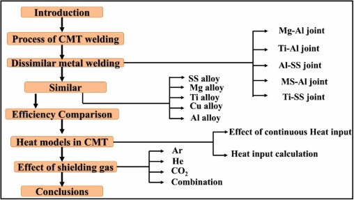
Dissimilar metal joining is widely employed across various industries for specific applications where combining distinct metal properties is essential. In aerospace, this technique enables the creation of lightweight structures with optimized strength, addressing the unique requirements of different components in aircraft and spacecraft [1], [2]. In the automotive sector, dissimilar metal joints contribute to weight reduction, improved fuel efficiency, and the integration of materials with diverse characteristics for enhanced vehicle performance. In nuclear engineering, these joints are critical in constructing components capable of withstanding extreme conditions, managing heat dissipation, and optimizing neutron absorption. The versatility of dissimilar metal joining ensures tailored solutions in each industry, addressing specific challenges and contributing to advancements in technology and material science [3]. New welding phenomena must also meet industrial standards. Austrian company Fronius invented CMT welding in 2004. [4], [5]. CMT welding is a tweaked Metal Inert Gas/Metal Arc Gas (MIG/MAG) process [6]. Compared to the traditional MIG, only 10% of the heat input is used in the CMT process, so the name is 'Cold' [7]. The approach focuses on the step-by-step pave layer theory, improving the welding joints' solidification process resulting in grain refinement [8]. Post-welding, a heterogeneous microstructure, necessitates precise heat treatment. Controlling temperature and time is crucial to attain the desired microstructure and mechanical properties for dual-phase weld joints (DWJ). Stabilizing the microstructure is essential for effective performance in ferritic/martensitic-austenitic joints under elevated temperature and pressure, achievable through appropriate post-welding heat treatment [9]. This three-phase low-temperature welding equipment uses gout transfer to reduce molten material (spatters) drops at joints [10]. Recent experiments have revealed that CMT has a low dilution level (3-4%) for welding hard materials like Stellite 21 on substrates like H13 steel, making it acceptable for hard-facing turbines and other applications [11]. At an equal filler wire rate, the CMT process of aluminum alloy resulted in lower weld dilution than typical GMAW [12]. CMT has 100% content efficiency [10]. CMT welding is used in aircraft, bridges, locomotives, microelectronics devices, and steel constructions due to its high tensile strength, better joint microstructure, and ability to weld dissimilar composites [13], [14]. Apart from the traditional process, the procedure includes a range of arc modes, viz., the pulse CMT (CMT-P), the advanced CMT (CMT-ADV), and the advanced pulse CMT (CMT-PAD) [15]. As the CMT technique, an advanced welding process has found application in many industries, the research on this technique is continuously attempted for improvement. This research is focused on understanding the effect of various parameters (like current, welding speed, and shielding gases) on different metals while making the joint. Moreover, the study of the heat input model is also done to understand the feasibility of simulation of this process in the future. Schematic of this research is presented in Fig. 1.
 Fig. 1
Process of CMT welding
Using a high-frequency pulse, the CMT transfers molten metal droplets in the weld zone. As the droplet of metal is transferred, the arc is quenched momentarily, minimizing heat input to the workpiece and lowering burn-through and distortion [16]. CMT uses "reverse polarity" to create a stable arc at a low current for a better weld. A unique shielding gas mixture with a small amount of helium stabilizes the arc and reduces spatter in the CMT process. CMT welding is a fast, precise method for welding thin materials like sheet metal and dissimilar materials [17], [18], [19]. The process of the welding cycle comprises three stages: The peak current phase, The background current phase, and the voltage short-circuiting phase [20], [21], [22]. After the short circuit current phase, a microprocessor retracts the filler, breaking the circuit and reducing heat input during joint settling. This truncated (low) heat input reduces inter-metallic layer thickness, improving joint performance. The current pulse frequency and wire retraction directly affect grain size and joint tensile strength. [23], [24], [25], [26], [27]. According to Mezrang et al. [14], the intricate welding current waveform in the CMT cycle and filler wire's back feeding that physically promotes metal transfer make it challenging to understand the relationship between welding parameters, metal movement, and heat movement. Thus, researchers have yet to study how heat and metal transfers affect the CMT current waveform as a function of parameters. CMT can rapidly outperform conventional welding in many manufacturing applications due to fine sheet width at joints, superior arc length control, and high edge coupling tolerance [28].
Welding of dissimilar metals by the CMT process
This section focuses on the feasibility of various dissimilar metal joints by the CMT process. The study yielded a comprehensive analysis of the feasibility of dissimilar welding in terms of metallurgical and mechanical properties.
Welding of magnesium (Mg) and aluminum (Al) alloy
Wang et al. [29] did not observe any welding defects. At the same time, they studied the dissimilar joint of AZ31 and AA1060 because low heat input and rapid heat transfer process in the weld led to the inhibition of the formation of hard intermetallic compounds (IMCs). Incorporating Si and utilizing meager heat input restrained the formation and expansion of brittle IMCs within the weld metal, enhancing joint strength. A distinct multilayer microstructure emerged in the fusion zone proximate to the Mg substrate, encompassing a solid solution, eutectic structure Mg2Al3, and Mg17Al12 layer. However, this intricate microstructural composition adversely affected the joint's strength, resulting in fracture during tensile testing. The fracture analysis revealed three characteristic modes of brittleness, underscoring the complex interplay of alloying elements, heat input, and microstructure in influencing the mechanical properties of the joint. The comprehensive optical microstructure of the joint was presented in Fig. 2, revealing distinct features between the substrate and weld metal. The weld metal exhibits a complex segregation microstructure. This complexity arises from the super-low heat input associated with the CMT welding process, facilitating rapid and controlled heating and cooling cycles. The abbreviated exposure to elevated temperatures prevents sufficient mingling of Mg and Al, consequently impeding the formation of the Mg–Al intermetallic compound. Microscopically, three discernible zones, labeled A, B, and C, were evident in the weld metal's structural composition, as depicted in Fig. 2a. Within the C zone, occasional instances of shrinkage porosity were observed, attributed to the broad spectrum of solidifying temperatures.
 Fig. 2
Further inspection of Fig. 2 highlights distinctive characteristics in each zone: the A zone was predominantly characterized by white columnar dendrite crystals, the B zone exhibits equiaxial crystals, and the C zone displays polygonal particles dispersed within the matrix. This intricate microstructural analysis provides valuable insights into the welding process, elucidating the impact of temperature dynamics on alloy composition and the resultant structural morphology. The distinctive features observed in each zone underscore the nuanced interplay between heat input, solidification behavior, and alloy composition during the CMT welding process, offering a comprehensive understanding of the joint's optical microstructure.
Jing et al. [30] fabricated a dissimilar weld using CMT of AZ31B magnesium and 6061 aluminum alloy. The presence of Si caused higher melting towards the Mg side due to its higher affinity to mix with Mg, forming Mg2Si. Moreover, The researchers observed that the joint shows a sudden peak in hardness in the fusion zone adjacent to Mg base metal due to eutectic reaction during solidification leading to the formation of α- Mg solid solution and intermetallic γ(Mg17Al12) phase, which was confirmed by the XRD analysis. This resulted in a sudden increase in the hardness of the weld joint, as depicted in Fig. 3. The amount of intermetallic phase affected the joint's tensile strength, causing failure at the joint with a brittle fracture. Madhavan et al. [31] employed four heat inputs to weld aluminum alloy A6061-T6 and AZ31B for lap joints using CMT welding. AlSi5 was utilized as a filler wire. The approach investigated joints' mechanical, metallurgical, and corrosion properties. The authors found that heat input affects residual stress, tensile strength, and corrosion resistance. Heat increased these characteristics significantly. Heat propagating through the bead's thickness uniformly cooled the joint, reducing residual stress. Due to insignificant cooling rate differences between the top and bottom layers, the microstructure is finer, strengthening the weld connection.
 Fig. 3
Dynamic corrosion testing examined pitting corrosion resistance. Mg2Si and Al6Mn intermetallic increased corrosion resistance due to high heat input. Wang et al. [32] joined the AZ3B with 6061 aluminum alloy by the variable polarity of the CMT welding technique, Electrode Positive/ Electrode Negative (EP/EN) ratios with different welding parameters, and ER4043 as a filler wire was used. With a declining EP/EN proportion between 4:1 and 1:4, the weld penetration of filler decreases. The thickness of IMCs near the AZ3B and weld zone decreases with a decrease in the EP/EN ratio. The effect of intermetallic layers can be seen in the microhardness value as the value peaks due to its hard and brittle nature. The decrease in the EP/EN ratio helps improve tensile strength, which increased considerably by over 100%. However, the fracture in the joints was brittle due to the formation of intermetallic. The weld pool carried significant volumes of Mg-rich intermetallic in the region close to Mg plates. Hence, the hardness values showed peaks in the fusion zone due to the uniform presence of intermetallic, which are hard and brittle. This caused the brittle failure of the joint when tested for tensile strength, having joint strength lower than any of the base metals.
Welding of Titanium alloy and Aluminum alloy
Tian et al. [33] employed Ti-6Al-4V and AlSi5 wires for DC CMT welding for wire and arc additive manufacturing, as shown in Fig. 4. As laid out, the Al alloy displayed metallic luster and flawless deposition, whereas the Ti alloy had uneven layers and grooves. The limited heat conductivity of Ti alloys caused uneven surface temperature. The authors clearly explained both alloys' solidification and interface. Diffusion of Si and Ti atoms in distinct zones caused the contact to produce intermetallic. Si diffusion in the Ti matrix formed Ti7Al5Si12 on the Ti side of the WAAM, while Ti diffusion in the Al alloy matrix formed Ti (Al1-xSix)3. Residual stresses during solidification caused the interface to break because of the significant disparity in the thermal characteristics of both alloys. Brittle Ti(Al1-xSix)3 also helped the crack spread. Sun et al.[34] used CMT and axial magnetic fields to make dissimilar Al/Ti joints—a magnetic field examined weld arc and droplet transfer. Researchers switched to alternating current. The Lorentz force caused by the magnetic field affected arc morphology. This force rotated the arc from the weld pool, increasing the molten area, which can be controlled by alternating current. The magnetic field increased shear tensile strength and changed the fracture location. The thin interface intermetallic layer increased tensile strength compared to CMT welding. Cao et al.[35] lap-joined A6061-T6 with 1 mm Ti-6Al-4V. Two experiments were made by swapping plates. The filler wire was ER4043. Both welds differ due to the alloy's thermal properties. Keeping the Al plate on top was difficult due to spray and distortion. For molten Al and Si, Ti is more wettable and spreadable than Al. The Ti plate on top produced crisp weld beads, smaller spatter, and less deformation. The joint's microstructure showed welding and brazing. Brazed joints between the Ti plate and molten Al filler were discovered. The investigation found intermetallic layers between molten Ti and Ti plates in the weld pool.
 Fig. 4
The cooling rate made the intermetallic layer thicker than the outermost layers. Al metal's HAZ failed due to the joint's lower tensile strength than Al base metal. Microhardness showed Mg2Si dissociation softened Al alloy. Li et al. [36] used AlSi5 filler wire to weld pure titanium and aluminum using CMT. To study weld metallurgy, researchers changed plate placements and wire feed rates. The metallurgical behavior of the joint suggests that both lap joints are fusion welded and brazed. The plate orientation modified the intermetallic layer thickness. Due to the thinner intermetallic layer, the junction with the Al plate on top had higher strength than the Ti plate on top joint. Table 1 summarizes the dissimilar Ti Alloy/Al done by the CMT welding process.
Table 1. List of studied dissimilar metal welding of Ti Alloy/Al alloy using CMT.
| Author | Base metal | Filler wire |
|---|---|---|
| [33] | Titanium (Ti-6Al-4V) and aluminium alloy (AlSi5) | ER4043 of 1.2 mm diameter and Ti-6Al-4V |
| [34] | Titanium (TC4) and aluminium alloy (A16061-T6) | ER4043 of 1.2 mm diameter |
| [35] | Titanium (Ti-6Al-4V) and aluminium alloy (A6061-T6) | ER4043 (AlSi5) of 1.2 mm diameter |
| [36] | Titanium (TA2) and aluminium alloy (A6061-T6) | AlSi5 of 1.2 mm diameter |
Aluminum alloy and Austenitic stainless steel
Babu et al. [37] tested CMT's hybrid manufacturing process welding and friction surfacing on lap layouts of austenitic stainless steel (ASS, AISI 321) and aluminum (AA2219). Friction stir processing was applied for aluminum coatings on stainless steel sheets, as seen in Fig. 5. Coatings were made from 20-mm-diameter aluminum rods. The experiment varied horizontal feed rate, rotational speed, dwell period, and axial force. These values enabled 1.2 mm coating. CMT creates aluminum-coated stainless steel-aluminum lap joints. Welding coatings with 0.6 mm aluminum covering resisted the highest shear tensile strain of 260 N/mm2 (Fig. 6) due to the heat input in the CMT process left the optimal amount of coating after melting, whereas eccentricity during testing reduced joint strength in the 1.2 mm coating. In Fig. 6, the boundary between the weld metal and coating displays favorable metallurgical bonding with a fine dendritic structure in joints (0.6) and (1.2) (Figs. 6b and 6c). However, joint (0.3) lacks this interface due to the complete melting of the Al coating during CMT welding (Fig. 6a). The unmelted Al coating measures 50-100 µm in the joint (0.6) and 200-400 µm in the joint (1.2) (Figs. 6b and 6c). Varied coating thickness in joints (0.6) and (1.2) results in distinct wetting and fusion characteristics of the weld metal. The interface between the Al coating and SS base metal exhibits robust bonding with a sharp zig-zag pattern, deliberately prepared before friction surfacing to enhance bonding and strength. Thin unmelted Al coating (50-100 µm) in the joint (0.6) significantly improves joint strength. However, excessive unmelted Al coating in the joint (1.2) is undesirable, potentially causing loading eccentricity and compromising joint strength. Attention to coating thickness and bonding characteristics is crucial for optimizing the strength of the final joints.
 Fig. 5
 Fig. 6
Liu et al. [38] used CMT and an external axial magnetic field (EMF) welded 5A06 aluminum alloy and 304 stainless steels. The EMF rotated the welding arc, increasing the metal heating area and pre-heating the base metal, which improved the outcomes. EMF also altered weld morphology. It decreased the thickness of the brittle iron/aluminum (Fe/Al) IMCs layer and prevented Fe dilution. Joint tensile strength improved. All EMF-welded samples were stronger than the best joint without EMF. The best joint employing EMF increased joint strength by 45% over a non-EMF aluminum/steel joint. Table 2 summarizes the dissimilar Al alloy/Stainless steel done by the CMT welding process.
Steel and Aluminium alloy
Mezrang et al.[39] manufactured steel-aluminum welds using zinc-coated low-carbon steel DC01 and 6016-T4 alloys. The 1.2-mm welding wire was ER4043. Pure Argon was used as an inert gas at 12 l/min to weld. Fig. 7 shows lap joint welding with a 10 mm cycle aluminum overhang on top. Fig. 8 depicts the CMT mechanism. It melts and deposits filler metal with little heat by alternating filling wire feed and arc current in a regulated wave pattern. The pulse phase's high-energy electrical arc melts the filler wire's tip. When the filler wire is added to the aluminum sheet, the "wait phase" begins. Under a weak arc current, short-circuiting and arc collapse before the layer impacts. Retracting the wire injects a liquid metal droplet, which leads to re-ignition and restarting of the cycle.
 Fig. 7
 Fig. 8
Sravanthi et al. [9] welded H32 5052 aluminum-galvanized mild steel nexus using GMAW-brazing and CMT. The prime focus of the research was to compare the corrosion behavior with the aid of welding parameters (e.g., welding speed and wire feed rate). Corrosion testing was carried out following ASTM G 67-04. Lap joints are built with Al-5%Si filler, and the samples after the corrosion test were studied with the help of Scanning Electron Microscopy microstructural characterization, Nano-indentor hardness measuring, and XRD technique phase analysis. The study shows a severe impact on intergranular corrosion irrespective of both processes. Further deduced that the intermetallic layer's thickness directly relates to heat input. Singh et al. [40] studied welding aluminium (AA5052) and steel (DP780). A unique CMT + P weld-brazing method was used to lap-weld. The researchers attributed the change in bead geometry and wetting angle to extra heat transfer from the thicker aluminum plate, which reduced wetting. The fusion zone/steel junction formed IMCs in the metallurgical investigation. Due to Fe and Al's low solubility, the ternary combination Fe-Al-Si generated intermetallic. The availability of base metal elements thickened this intermetallic layer with an increased wire feed rate. Due to their brittleness, these IMCs propagated cracks through layers, producing failure at lower loads and affecting shear and tensile strength. Silvayeh et al. [41] welded 1.15-mm-thick aluminum alloy (EN AW 6014 T4) to 0.8-mm-thick galvanized dual-phase steel (HCT 450 X + ZE 75/75). Six aluminum-based filler wires were evaluated. The study found that filler wires dominate microstructures more than welding settings. Higher Si-based alloys limit intermetallic formation, but the effect of Mg variation in filler wire is undetermined.
Yang et al. [26] fuse zinc-coated carbon steel to aluminum alloys using CMT. A 1.2 mm diameter ER 4043 was used as filler wire. As the researchers reported, zinc vaporization from steel produced various problems, e.g., caused wavy edges, porosity, and absence of side wall and root fusing. Si in filler wire dissolves intermetallic in the metal matrix, forming a thin intermetallic layer. Intentionally spacing between the plates allowed the vapors to escape the molten pool. This improved fusion and lowered the bonding angle. The joint's tensile shear strength properties also showed improvement. Niu et al. [42] lap joined 1 mm AC 170 PX Al alloy to 1.2 mm ST06 Z galvanized steel using CMT advanced welding. ER 4043 and ER4047 were used as fillers. ER4043 lap joints had a lower wetting angle, longer bonding duration, and better weight than ER4047 lap joints under the same conditions. EPMA was used to predict phases. The bead's low wettability caused the weld zone failure in tensile shear strength tests. ER4043's fractography indicated mixed failure, while ER4047's showed ductile failures with significant dimples. Cao et al. [43] studied lap-joint welding of aluminum alloy and galvanized mild steel with 1 mm thickness. Taguchi method was used to construct the experiment design with seven factors and 3 level variations. The quadratic regression model optimized parameters for joint strength as a measure. The microstructure indicated solely Fe and Al intermetallic. Due to strong arc heating, zinc was absent. The dissimilar mild steel-aluminium alloy joint was as strong as an Al-Al similar metal joint. The microhardness test confirmed that HAZ softening reduced strength compared to Al base metal. Table 3 summarizes the dissimilar Steel/Al alloys done by the CMT welding process.
Table 3. List of studied dissimilar metal welding of Steel/Al alloy using CMT.
| Author | Base metal | Filler wire |
|---|---|---|
| [39] | Aluminium alloy (6061-T4) and zinc-coated mild carbon steel. | ER4043 of 1.2 mm diameter. |
| [9] | H32 5052 Aluminium alloy and galvanized mild steel. | Al-5%Si of 1.2 mm diameter. |
| [40] | Steel (DP780) and aluminium alloy (AA502). | AlSi5 of 1.2 mm diameter. |
| [41] | Aluminium alloy (EN AW 6014 T4) and galvanized dual-phase steel (HCT 450X + ZE 75/75). | Commercial filler alloys (EN AW 5183, EN AW 5087, EN AW 6082, Al-3Si-1Mn), self-produced filler alloys (Al-4Mg-0.6Sc, Al-0.3Mg-0.5Sc-0.4Zr, Al-0.3Mg-0.4Sc-0.3Zr). |
| [26] | Aluminium alloy (6061-T6) and thick-coated low-carbon steel. | ER4043 of 1.2 mm diameter. |
| [42] | Aluminium alloy (AC 170 PX) and ST 06 Z galvanized steel. | ER4043 of 1.2 mm and ER4047 of 1.2 mm diameter. |
| [43] | Aluminium alloy and galvanized mild steel (AA6061, AA7075 and AA5183) | Al4043, Al4047, and Al5356 of 1.2 mm diameter. |
Titanium alloy and stainless steel
Mou et al. [44] used variable polarity. CMT using ERCuSi wire and adjusting arc brazing polarity reduces Ti-Fe intermetallic brittleness in Ti-6Al-4V/304 L joints. By altering the electrode positive/electrode negative (EP/EN) ratio, they evaluated the impacts of the temperature profile, penetration ratio, tensile strength, and microstructure on CMT welding. Lower EP/EN ratios delivered high energy to the wire, reducing high-temperature holding time. The ratio range was a record 8:1 to 1:8, lowering the width of the Ti5Si3 intermetallic layer and the Ti-6Al-4V/seam transition zone's Ti-Cu interlayer to 81 μm from 118 μm. Joint tensile strength declined from 216.89 to 211.29 MPa. As EP/EN increased, the Ti5Si3-layered Ti-64Al-4V/seam transition zone thickened. Both conditions reduced welding spot tensile strength. EP/EN=8:8 gave the best tensile strength. EP/EN improves transition zone thickness for an acceptable transition zone and narrows the Ti5Si3 layer. Each trial had reduced joint tensile strength. At EP/EN = 8:8, a small transition zone with a thick Ti5Si3 layer had the highest tensile strength as shown in Fig. 9. Mou et al. [45] examined the mechanical characteristics and microstructure of CMT weld brazed Titanium alloy (TC4) to ASS (304 L) utilizing a V-shaped groove for butt joints and 3-stage filler wire feed speed variation. This study uses ERCuSi-A filler wire. Higher wire input rates increased joint strength, yet all joints showed brittle failure. 5.5 m/min wire feed rate with high heat input produced the strongest joints. Microstructure evolution depended on wire feed speed and torch offset. The highest heat input had a three-fold thicker Cu-Ti contact than the lowest. Wire feed rate has a distinct effect on the Cu-Fe interface. As heat input increases, intermetallic formation decreases due to greater melting of the SS plate and mixing in the weld pool. Pardal et al. [46] successfully welded Titanium AMS4911l with 316 L stainless steel by CMT process in butt joint configuration. Their thickness is 2 mm. The researchers found that the weld bead could not wet the SS plate with a low wire feed rate, causing an undercut in the SS-weld zone junction. This later affected the tensile strength of the joint as joints with lesser wettability had lower strength.
 Fig. 9
The metallurgical study showed that IMCs couldn't be avoided, although the IMs formed with Cu bead are more ductile than Fe-Ti IM. Chang et al. [47] used a lap joint to weld Titanium (TA2) and galvanized steel Q235. Additionally, they were compared to lap joints of similar materials. Titanium's thermal conductivity was found to be poor based on the weld appearance of all four joints. Due to the IMCs of Cu-Fe-Ti, the top steel-bottom titanium joint's microhardness was higher at the Ti interface than weld metal and base metal. The top steel-bottom titanium joint's tensile force reached 93% of the steel-steel joints. From the Ti-weld metal interface, the top Ti-bottom steel fractured. Both fractures occurred in the steel base metal in the top steel-bottom, Ti, and steel-steel joints. Table 4 summarize the dissimilar Ti alloy/Stainless steel done by CMT welding process.
Table 4. List of studied dissimilar metal welding of Ti alloy/Stainless steel using CMT.
| Author | Base metal | Filler wire |
|---|---|---|
| [44] | Titanium alloy (Ti-6Al-4V) and stainless steel (304 L) | ERCuSi-A of 1.0 mm diameter |
| [45] | Titanium alloy (TC4) and stainless steel (304 L) | ERCuSi-A of 1.0 mm diameter |
| [46] | Titanium alloy (AMS 4911 L, Ti-6Al-4V) and stainless steel (AISI 316 L) | CuSi-3 of 1.0 mm diameter |
| [47] | Titanium alloy (TA2) and galvanized mild Q235 steel | ERCuNiAl of 1.2 mm diameter |
Welding of similar metals by the CMT process
This section focuses on the feasibility of various similar metal joints by the CMT process. The study yielded a comprehensive analysis of the feasibility of dissimilar welding in terms of metallurgical and mechanical properties.
AISI 304 stainless steel
Tang et al. [48] coated 304 ASS with Ni-based and Iron-based fillers via CMT to improve wear and cavitation erosion resistance. The coating's cumulative loss for volume/weight was reduced by one order of magnitude than the substrate's. Fine dispersed carbide and toughness increase the wear resistance of an iron-dependent coating, while significant phases of nickel-based coating aid corrosion resistance and cavitation erosion. CMTed samples of iron- and nickel-based coatings were cross-sectioned to compare microstructure. Fig. 10 (a) and (b) illustrates variations in grain size and the interface between solidified droplets in the iron and nickel-based coating, indicating localized heat dissipation effects. This inhomogeneity results in a few larger grains at the interface, influencing the longitudinal heat dissipation of the coating and contributing to increased G/R ratio and grain size. In Fig. 10 (c) and (d), the influence of misorientation angles is evident, primarily governed by Low-Angle Grain Boundaries (LAGBs), a common characteristic in cladding coatings. The nickel-based coating in Fig. 10(c) displays a polarized distribution of LAGBs, virtually devoid of High-Angle Grain Boundaries (HAGBs) [48]. Conversely, the iron-based coating in Fig. 10(d) exhibits increase in the fraction of HAGBs, potentially attributed to the transformation of the recrystallized texture mentioned earlier. HAGBs are recognized for impeding dislocation motion and enhancing material toughness, suggesting the suitability of the iron-based coating for wear environments. The iron-based coating demonstrates a significantly smaller average grain size (1.26 μm) than the nickel-based coating (1.88 μm).
 Fig. 10
.1. Magnesium AZ91 alloy
The lightweight nature of magnesium makes it prone to forming large droplets, leading to spatter if these droplets fall outside the weld pool. The risk is amplified as overheated droplets tend to explode due to the narrow temperature range between magnesium's melting and boiling points [49], [50]. Additionally, magnesium alloys are susceptible to various challenges during welding, including grain coarsening, oxidation, evaporation, thermal stress, and hot cracking. To ensure a stable welding process and achieve favorable as-weld properties, precise control of heat input becomes crucial. Despite existing studies on the CMT process with magnesium alloy wire, there needs to be more understanding of the arc stability in CMT joining processes with magnesium alloy wire [51].
The contact angle at which the weld bead interacts with the substrate is pivotal in CMT applications, particularly in repair welding. This angle directly influences the ease of accumulation of consecutive passes, making it a critical parameter in welding. The cladding appearance under various welding process parameters is revealed in Fig. 11. The advantage of low heat input in the CMT process, while beneficial in specific applications, can pose challenges in cladding. The CMT process's low heat input during cladding can produce weld beads with smaller contact angles. The evaluation revealed that the contact angle increased with an increase in Wire Feed Speed (WFS) for both CMT modes. This phenomenon can be attributed to the higher deposition of material per unit and increased heat input associated with a higher WFS. The additional heat input provides a greater driving force for the molten weld pool to spread across the substrate's surface, resulting in a larger contact angle [52]. In the case of DC-CMT, the contact angles at WFS values of 3 to 5 m/min were all below 90°. When the contact angle approaches 90°, the welding arc for the next pass becomes unstable. This instability manifests as the arc jumping between the reinforcement and the base metal, occasionally leading to a lack of fusion between clads [53]. Pulsed-CMT also exhibited undesirable contact angles at a WFS of 3 m/min. However, at a WFS of 4 m/min, a contact angle of 117° could be achieved. Studies by Ola and Doern [53] suggest that a contact angle greater than 115° is more conducive to adding successive passes. Beyond a WFS of 4 m/min, an unstable welding arc and the resultant poor appearance became undesirable for cladding. Consequently, pulsed CMT with a WFS of 4 m/min emerged as a viable option for multipass cladding of light metal alloys, striking a balance between contact angle and arc stability.