1. Introduction
The climate emergency means we need to find immediate solutions to reduce the greenhouse gas emissions. The building sector has to play a significant role in this reduction, given it is responsible for 35% of the total consumption of energy and 38% of greenhouse gas emissions globally [1]. To achieve reductions in energy consumption, improving the energy efficiency of buildings through renovation is needed. In the EU, this for instance emphasised in the European Green Deal (Communication 2019/640) and the associated Renovation Wavestrategy [2]. Similar initiatives for improving the sustainability of and decarbonising the building stock can be found, e.g. in the U.K [3] or the U.S.A [4] where recent polices addressing the renovation of buildings have been implemented. Similarly, in developing countries with significant and rapid improvement of living standard, e.g. India and China, policies for improving energy efficiency standards are being implemented. In China (where the total building floor area doubled between 2000 and 2015 [5]), the Technical standard for nearly zero energy buildings was implemented in 2019 [6], while in India, the Bureau of Energy Efficiency (BEE) has developed a labelling scale for residential buildings to provide information to consumers about the energy efficiency program standard of the homes to be built across the country [6]. The latter is estimated to lead to energy savings up to 40%.
The ageing of the existing building stock also means that a considerable percentage of it has been constructed to outdated building codes and seismic standards [7]. This poses a great societal risk, as highlighted by the vulnerability of the existing building stock to recent earthquakes, leading to structural damage, significant economic losses, but also to severe injuries and loss of human lives [[8], [9], [10], [11], [12]]. As more buildings approach the end of their conceived-for service life, other risks related to durability of materials also emerge, including excessive corrosion of steel reinforcement or structural steel members which can greatly decrease the capacity of structural elements and even result in their collapse [13,14]. Structural retrofitting may hence not be only required in earthquake-prone areas, but to a larger proportion of EU buildings.
Given the scale of the problem, addressing energy-inefficiencies and structural deficiencies of existing buildings through their replacement is not a viable option, as it would have a severe impact on the existing urban fabric and society, and would not be financially feasible or environmentally sustainable. Instead, preference should be given to the lifetime-extension of existing buildings through maintenance, repair, and renovation. Given that there is a large proportion of buildings in need for upgrading [15], the scale of refurbishment works and required investments is however significant. Uptake of renovation is however still low, for instance annual renovation rates are ranging between 0.4 and 1.2% in EU countries [16].
To promote renovation and ensure the longevity of energy upgrading investments, a holistic approach to building renovation could be instrumental. Until recently, repair and renovation efforts and related policies were however mainly directed to the energy upgrading of buildings alone, without taking into account their structural integrity. Promoting such a holistic view on building renovation is crucial, as disregarding the structural integrity of a building may cause misleading expectations on actual savings for an energy-retrofitted building, as energy upgrading alone does not lead to any reduction in structural vulnerability. Investments in energy efficiency measures may be completely lost if a structure is damaged or collapses, e.g. in the event of an earthquake [17]. Similarly, seismic retrofitting interventions alone could compromise thermal comfort if a building's energy efficiency is not considered.
In the scientific literature, the topic of integrated seismic and energy retrofitting has gained traction over the last five years. New methodologies are required for combined assessments of existing buildings, as well as for evaluating the potential benefits from integrated interventions. Including energy efficiency and seismic resilience (e.g.: [18], as well as life-cycle costs (e.g.: [19]8) in the assessment of existing structures is critical for informing the decision-making process in building renovation. To address the technical feasibility of integrated retrofitting implementations, different materials and technologies have been proposed by various research groups and an overview of their developments is presented here. This paper presents the first state-of-the-art review on the emerging scientific research on materials and technologies for integrated seismic and energy retrofitting. An analysis and comparison of the presented technology options is then presented based on the involved costs, the environmental impact of the materials, occupancy disruption and down-time due to the interventions are compared. Finally, potential economic benefits, as well as the technical and financial barriers for the implementation of integrated retrofitting are discussed, followed by a brief overview of incentives and regulatory frameworks that may help to overcome said barriers.
2. Integrated retrofitting concepts and technologies
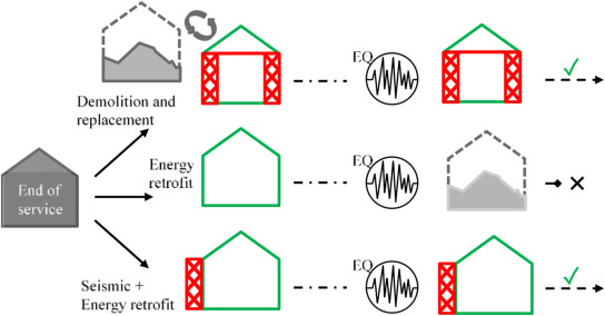
Structural and energy retrofitting of an existing building have so far generally been treated independently. A detailed description of such separate seismic or energy efficiency retrofitting solutions are not within the scope of this paper and the reader is referred to recent state-of-the-art reviews on these topics [[20], [21], [22], [23], [24], [25]]. In regions with seismic hazard, the two needs of retrofitting (structural and energy) are however inherently linked, given that seismic damage or collapse would also affect the safety of the energy renovation investment. Fig. 1 compares demolition and replacement of an existing building with two different retrofitting approaches for an existing building. In the first one, only energy retrofitting is applied, which leaves it vulnerable to a potential seismic event. In the event of an earthquake within the structure's lifespan, the occurrence of damage is likely, given that the structural deficiencies have not been addressed. Depending on the intensity of the event, the consequences may range from the need for minor repair works to the total replacement of the building. Obviously, in such a case, along with the building itself, the energy retrofit is affected and might be lost as well.
 Fig. 1. End of service life of buildings: The effect of (1) Demolition and rebuilding; (2) Energy upgrading and (3) integrated energy and seismic upgrading in zones of seismic hazard (based on: [17].
On the other hand, if an integrated structural and energy upgrading scheme is applied, then the building's structural integrity can be regarded as safe with regards to the designed-for level of seismic intensity. This means that even if a major seismic event takes place, the building will be able to withstand it, without affecting the energy retrofit at all. Practically, in areas of moderate to high seismic risk, it is imperative that any energy retrofit application should only be carried out if the building can be considered structurally safe, according to modern standards. Otherwise, the risk of losing the energy investment is not justifiable as recent experience has shown [17].
The need for combined energy and structural retrofitting is nowadays acknowledged and has been reported by researchers in the field [17,18,26,27]. The application of an integrated retrofitting solution could be as simple as combining two independent techniques of structural and energy upgrading. In the case of simply combining two separate interventions, the total cost of the intervention would however be approximately equal to the sum of the two independent interventions, making such solutions less economically viable then techniques that can achieve both goals at the same time in an integrated fashion and hence at a lower cost.
When thinking of combining techniques for seismic and energy retrofitting, it is important to consider their compatibility already at the design phase, particularly in terms of possible spatial overlapping; the scale of application; the level of disruption; and the desired performance level. Spatial overlapping can hinder the application of either the seismic or the energy retrofitting intervention due to practical constraints they cause each other. The scale of application is related to the number of building components on which the intervention is applied, while the level of disruption is related to the building downtime during which the intervention works must be realised. For instance, if the seismic intervention is needed only on few members of a building, while the energy intervention is foreseen to require works on the entire building, the two interventions may be considered less compatible in terms of scale, but likely also on the level of disruption. Recently, a framework for combining seismic and energy retrofitting interventions was proposed by Menna et al. [28]. In this framework, attention is placed on ensuring compatibility between seismic and energy retrofitting techniques according to their respective performance target, their level of disruption and intrusiveness, and time and cost of the respective intervention. The proposed framework hence aims to ensure that seismic and energy upgrading interventions with similar disruptiveness, cost and construction time are combined to achieve specific seismic and energy performance targets. The latter are defined in terms of an improvement in safety index (ζE = PGAC/PGAD) at the life safety limit state (SLV) according to the Italian Building code [29], and in terms of the reduction in primary energy consumption (PEC) achieved by the intervention, respectively.
Integrated techniques aim to achieve energy and seismic performanceimprovement at once, with a single system or material, guaranteeing the required performance levels both in terms of seismic safety and energy efficiency. While this requires a more in-depth conception and design, integrated systems could reduce downtime and labour costs compared to combinations of separate interventions. Different types of integrated seismic-plus-energy retrofitting solutions are proposed in the scientific literature and can be broadly grouped into:
-
●
Exoskeleton interventions;
-
●
Improvement of envelope elements to achieve higher energy and seismic performance;
-
●
Replacement of envelope elements by higher performance elements;
-
●
Combined interventions on horizontal elements, i.e. roof and floors.
Fig. 2 aims to provide an overview and categorisation of the identified combined retrofitting technologies.
 Fig. 2. Categorisation of combined retrofitting technologies.
While not all the interventions presented here-in are fully integrated systems, the studies selected all display a certain degree of integration between the structural and energetic components or show a strong potential for integration. Completely separate interventions, e.g. base isolation combined with energy upgrading of a building, are however out of the scope of this review.
2.1. Integrated exoskeleton solutions
An exoskeleton is an external self-supporting system (i.e. with its own foundations) rigidly linked to an existing building that is vulnerable to seismic actions [30]. Since the 1980s the use of external auxiliary structures is considered one of the possible options for providing additional strength and stiffness to existing RC buildings with low dissipative capacity. It is possible to divide structural exoskeletons into two main categories: (i) wall-like systems (introducing shear walls or braced frames Fig. 3a) and (ii) shell-like systems, as in Fig. 3b, exploiting a box-structural behaviour [26]. For a recent state-of-the-art report on the use of structural exoskeletons, the reader is referred to Di Lorenzo et al. [31].
 Fig. 3. (a) Wall and (b) shell layouts for structural exoskeletons.
The application of exoskeletons for building renovation can generate benefits of reducing building occupant disruption (being applied outside only), minimising post-earthquake building downtime, elongating the building structural service life and reduce the environmental impact associated with seismic damage over the building life cycle [26]. Moreover, it gives the possibility for adding new storeys and to change the external appearance of the building and hence its aesthetics. This makes the exoskeleton solution of particular interest to the New European Bauhaus initiative. Still, exoskeleton solutions are not always applicable due to the need of space around the structure and need for an additional foundation system (e.g. not feasible in densely built-up areas) and significant change of external appearance of structure, which may not be desirable or allowed in some cases. Additionally, as forces are usually transferred from the existing building to the exoskeleton by means of connections at the floor level, if the horizontal diaphragm is not stiff and resistant enough, the intervention might not be effective.
As shown in Fig. 3, two main ways of integrating structural and energy upgrading within an exoskeleton can be envisaged. In wall systems the energy efficiency upgrade can be achieved by the finishing curtain walls or the envelope attached to the exoskeleton (Fig. 3a); in this case, the two structural-energetic systems work in parallel. On the other hand, in shell systems, the energy efficiency upgrade and structural safety could be achieved through a dual-use of the same elements (Fig. 3b).
The first combined retrofitting application appears to be the renovation of the Midorigaoka-1st building of the Tokyo Institute of Technology completed in 9 months without the need for tenant-relocation [[32], [33], [34]]. It made use of a shell exoskeleton (Fig. 3b) combining Buckling Restrained Braces (BRB) for additional seismic energy dissipation capacity, and louvers for improved shading, hence reducing solar heat gains. An experimental study on representative RC frames showed the retrofit could prevent brittle shear failure and 2% inter-storey drift (ISD) was reached without any damage to the frame [34], while a simulation study showed reductions in solar radiation up to 66% through the louvers, with a reduction in annual energy consumption of up to 8% [35].
The use of steel-braced shear wall exoskeleton systems proposed by Marini et al. [26] (Fig. 4a) provided seismic strengthening while supporting separate energy efficiency systems (Fig. 4b). The latter includes solar greenhouses along the southern façade, as well as thermal insulation (EPS), new windows and shading systems (adjustable louvers) for solar radiation control. The proposed system was evaluated for a 1970s case study RC building through numerical analyses which showed significant improvements in seismic behaviour with a displacement capacity exceeding the demand at the life safety limit state (SLV) of the Italian Building Code [29], while stationary thermal analyses demonstrated a 70% reduction in heating energy consumption.
 Fig. 4. (a) Shear-wall structure; (b) energy retrofitting supported by the exoskeleton: adjustable louvers, solar greenhouses and filter spaces [36] - CC BY 4.0).
A similar system, using steel or timber frames was proposed [37], where additionally to thermal insulation, the external structure also provides thermal buffer zones, helping to reduce solar radiation in summer, providing solar heating in winter, and supporting plug-and-play installations for new HVAC systems, as well as generating additional living space in the form of balconies or extra rooms, depending on the user's needs. While the proposed retrofitting scheme was assessed to have a higher upfront cost compared to a deep energy renovation (+16.5%), the system can result in significant savings when considering the reduced need for resident relocation and the increase in real-estate value due to the increased living space and enhanced architectural value and user comfort. For a case study in Greece, based on seismic responsespectrum analyses, an exoskeleton with braced steel frames (with HEB 240 sections) acting as shear walls can achieve reductions in displacement demand (between 16 and 26%) at the design earthquake. Additionally, a reduction in energy consumption up to 75% in the winter months and overall reductions of 35% were reported based on simulations for three case study locations (Greece, Italy and Romania).
More recently Foti et al. [38] built a prototype dissipative frame element, shown in Fig. 5a, to be used as a modular “kit” that allows to seismically retrofit a building, to make it energy self-sufficient and, possibly, also produce energy (through photovoltaics). Similarly to the solutions described previously, the elements could also be used to host thermal buffer spaces, shading systems or rainwater collection modules. Within the external steel frame, buckling-restrained axial dampers (BRAD) can be installed for additional seismic protection of the building, as shown in Fig. 5b, which can act as replaceable “seismic fuses” concentrating plasticity and damage during an earthquake. For a case study 1980s residential building in Southern Italy, the seismic behaviour, evaluated through FEM, was shown to be improved with reductions in roof-drifts of 41.3% and 36.8% in the building's weaker and stronger directions, respectively. In terms of energy efficiency, significant reductions in energy consumption can be achieved, while, if installed, the PV panels can generate up to 100% of the energy consumption of the heat pump for heating and cooling.
 Fig. 5. (a) Prototype of an element of the dissipative frame exoskeleton with integrated photovoltaics (PV), (b) dissipative BRAD in the perpendicular frames [38] - CC BY 4.0).
An alternative integrated exoskeleton system can be achieved by using diagonal grids (“diagrids”) as exoskeletons, which contain directly façade elements for structural, energy and architectural improvements, as studied by Labò et al. [[39], [40], [41]] and D'Urso and Cicero [42]. From the structural point of view, the diagonal members are designed to intersect at the floors of the existing structure, where they are connected to steel horizontal ring beams, which have the double function to stabilize the diagrid exoskeleton and to collect and transfer the seismic forces from the building floor diaphragms to the diagrid and a new foundation system. Following the principles of Life Cycle Thinking(LCT), the diagrid can be fabricated from recyclable/reusable materials, and repairable, adaptable and fully demountable elements. An optimised designapproach for the diagrid members, aimed at minimising the impacts and costs of the intervention and throughout the life cycle of the building is presented in Ref. [40]. D'Urso and Cicero [42] implemented a parametric optimisationalgorithm to find the most material efficient diagrid exoskeleton and different design ideas for integrated retrofitting were then elaborated, as shown in Fig. 6, including renewable energy production (e.g. BIPVs), vertical gardens or “green walls” that contribute to passive cooling, and solar shading devices, e.g. louver systems, that provide control over solar radiation and natural lighting. In either case, the energy savings (or potential energy production, e.g. through solar panels), depend on the specific options chosen for the energy efficiency modules attached to the exoskeleton, hence in any case, both costs and energy savings can be assumed to vary largely.
 Fig. 6. Different design options for a holistic upgrading of RC building with a diagrid exoskeleton [42] - CC BY 4.0).
The concurrent seismic and energy upgrading can be also achieved by using RC frame exoskeletons [43], as in Fig. 7a, or by using precast auxiliary RC frames [44,45], as in Fig. 7b. The external RC members can be designed according to the local seismicity, while additional masonry infill walls ensure improved thermal insulation of the building. However, this intervention can be complemented with other energy efficiency solutions to make it suitable for more demanding climatic zones. The case-study building was evaluated numerically for locations in Italy with different seismicity (low, medium, high) in climatic zone E (covering the largest part of Italy). The energy demand was reduced from 74 kWh/year per unit area (energy performance class F), to about 43 kWh/year (class D), while the ratio of seismic capacity to demand could be improved from 0.38 to 1.38 (+263%) for a location of high seismicity.
 Fig. 7. (a) 3D view of a case-study structure with RC frame exoskeleton [43] - CC BY 4.0); (b) alternative using precast frame elements [44] - CC BY 4.0).
Similarly, a shell exoskeleton system using tightly-spaced, cast-in-place external RC frames, as shown in Fig. 8, and prefabricated EPS modules, which provide the formwork of the RC frame, as well as increasing energy efficiency, was recently proposed and is currently tested in the TIMESAFE project [46]. In an initial FEM pushover evaluation of a retrofitted frame, the yield force was doubled, while the displacement capacity increased by nearly 300%. At the same time, the U-value for a typical infill wall was shown to be potentially reduced from 1.86 to 0.15W/(m2K), as well as showing improvements in sound insulation through acoustic analyses.
 Fig. 8. RC-framed double skin solution [46] - CC BY 4.0).
Finally, constructing a new structural system with external foundations integrated with a thermal coating has been proposed by Pertile et al. [[47], [48], [49]]. The shell-exoskeleton system consists of a thin structural RC wall cast in-situ between pre-assembled layers of insulating material, functioning as permanent formwork (Insulated Concrete Formwork, ICF) and providing thermal insulation to the building envelope, as shown in Fig. 9. Note that the use of concrete makes this system not reversible or reusable, and potentially less environmentally friendly. The wall's reinforcement is designed depending on the building's characteristics and is connected with the existing structure at the beams of the structural frame (Fig. 9a) and at foundation level (Fig. 9b). The thermal transmittance in the case of using two polystyrene layers with 150 mm total thickness, is equal to U = 0.21 W/m2K, which is under the limit foreseen for climate zone F, corresponding to the coldest climate in Italy. Quasi-static cyclic tests on two RC frames and two masonry wall specimens upgraded with ICF demonstrated a good connection of the system to the specimens, but occurrence of brittle failure making it a non-dissipative system in the design calculations for seismic strengthening [48]. Finally, a numerical evaluation of the retrofit applied to different case study (masonry and RC) buildings demonstrated a reduction in displacement demand up to 85% at the SLV limit state [49].
 Fig. 9. Insulating concrete formworks: a) Connection of the system to storey beams and b) foundations based on (based on [48].
2.2. Integrated interventions on existing building envelopes
Given the large vulnerability and high energy transmittance of vertical building envelope elements (e.g. infill walls or structural masonry), particular attention is paid to intervening on external walls, strengthening the existing elements while additionally providing thermal insulation. Typical thermal retrofits nowadays use mineral wool, polyurethane (PUR) or polystyrene (EPS or XPS) as insulation materials, which have thermal conductivity values (λ) around 35 mW/m·K [25], while very low values of 3.5–8 mW/m·K can be obtained for Vacuum insulation panels (VIPs), or advanced materials like aerogel-incorporated plasters with λ-values between 10 and 15 mW/m·K [50,51]. Different avenues can be identified in the literature such as the application of composite materials or prefabricated panels, either cement-based or timber-based. Another type of solution consists in local strengthening of the existing openings integrated with substitution of old fenestration, when the latter have to be replaced. In the case of all envelope strengthening solutions, the increase in base shear capacity, as well as in shear forces acting on the existing frame, mean that a careful evaluation of the foundation and frame elements needs to be carried out, as these elements may need to be strengthened additionally.
2.2.1. Strengthening of existing infill or masonry walls with composite materials
Rather than constructing new building elements, an integrated structural strengthening and energy retrofitting intervention can be applied to the existing building envelope. For unreinforced load-bearing masonry walls or infill walls of RC-frame structures, strengthening can be applied to achieve a reliable structural response. From a seismic point of view, a retrofit intervention on the infills prevents the sudden brittle failure of unreinforced masonry (URM) walls or infills. Several strengthening solutions using composite materials have been tested and a summary is provided in Ref. [52]. These range from textile-reinforced mortars (TRM), fibre-reinforced polymer sheets, which are bonded using epoxy resins (FRP) and engineered cementitious composites (ECCs) or steel fibre reinforced mortars (SFRM), using short fibres dispersed in a mortar, to steel meshes for reinforcing thin layers of plaster.
The use of TRM in integrated seismic and energy retrofitting of building envelopes has been particularly investigated (e.g: [27,[53], [54], [55], [56]]. It is made of (high strength) lightweight textile fibre reinforcement (e.g.: carbon, glass or basalt bidirectional fibres with open-mesh configuration) combined with cementitious mortars. The application of TRM to concrete or masonry building envelopes is characterised by low invasiveness (as a plaster layer), and relatively easy workmanship. Next to its relatively low cost, TRM has a high strength-to-weight ratio and high compatibility and bond with concrete and masonry substrates [57,58]. Additionally, compared to FRPs, TRM has better performance in terms of fire resistance [53,59] and behaviour at high temperatures (e.g.: [[60], [61], [62], [63]].
As shown in Fig. 10, TRM can be easily applied together with different thermal insulation solutions. Bournas [27] explored the avenues of TRM for structural-plus-energy retrofitting solutions, proposing the combination of TRM with different, conventional or advanced, thermal insulation materials (e.g. TRM + Polyurethane (PUR), TRM + Extruded polystyrene (XPS), TRM + Aerogels, etc.), or the integration of capillary tube heating systems within the TRM. Different combinations can be used to provide improvements in structural, energy and (potentially) fire behaviour in one integrated application. Such a system can be used both in framed buildings (RC, steel) with masonry infills and in load-bearing masonry structures.
 Fig. 10. Possible configurations of TRM and energy upgrading solution: a) Infills and RC structure retrofitting with TRM, b) Insulation of a building envelope, c) TRM + capillary heating tubes and d) TRM + thermal insulation material [27] - CC BY 4.0.
In terms of experimental investigations, combined TRM and foamed polystyrene or foamed cement insulation were tested by Triantafillou et al. [53,54]. Various configurations of insulation and TRM-placements were investigated on masonry wallettes subject to out-of-plane loading and their fire behaviour was evaluated after their exposure to temperatures up to 870 °C [53]. It was found that the out-of-plane strength of masonry walls retrofitted with TRM and foamed polystyrene (+200–340%) was superior to that of TRM-strengthening alone (+170%), mainly due to the increased lever arm. In terms of out-of-plane deformation capacity, the combined system was again more effective than the TRM alone, with improvements by 140–145% [53,64]. The failure mode was textile rupture when the TRM was placed directly on the masonry surface, but debonding was observed when placed on top of the thermal insulation (e.g. Fig. 11). For those specimens which were first subjected to fire, the placement of the textile below the insulation layer proved to be more effective, provided that the insulation material is fire-resistant.
 Fig. 11. Debonding at the insulation–masonry interface (a) one layer; (b) two layers of insulation [64] - CC BY 4.0).
This retrofitting system was also found to be highly effective in improving the in-plane behaviour of masonry walls [54], testing two- or one-sided jacketing and placing the insulating panel either on the outer face or between the TRM and the masonry. The positioning of the TRM and the insulation material was found not to affect the in-plane response, as long as proper bond between the different layers was achieved. Moreover, single-sided application only led to a slight reduction in effectiveness, which is beneficial as it allows to perform all the work from the outside of the structure, drastically reducing the cost and the disruption of building occupancy.
Gkournelos et al. [55] tested the effect of in-plane damage on the out-of-plane behaviour of TRM-retrofitted masonry wallettes insulated with foamed polystyrene. Next to an improved in-plane behaviour, the out-of-plane capacity of the retrofitted specimens was significantly improved. Again, the out-of-plane behaviour of the combined seismic and energy retrofitted specimens presented a better behaviour than the TRM retrofit alone due to the increased lever arm. In the insulated specimens, debonding of the insulation was observed, which indicates that the quality of the insulation-to-masonry connection imposes an upper limit to the amount of force that can be transferred to the textile. This type of solution is also investigated on a RC full-scale building currently undergoing testing at the JRC's ELSA laboratory within the iRESIST + project [56].
In terms of energy performance improvements, case studies evaluated through building energy modelling (BEM) for different climatic conditions, have shown that large reductions in heating and cooling energy consumption can be achieved through applying thermal insulation together with TRM [52]. Savings in total energy demand varied with the original building's envelope material and climatic conditions of the case study location, with savings ranging between 37% for more recent construction (1970s and 80s) in warmer climates, up to 78% for older low-rise buildings placed in colder climatic regions.
Along the same lines, Giaretton et al. [65] also performed in-plane testing on clay brick masonry wallettes strengthened with different G-TRM configurations, including a specimen with an external thermal insulation layer. Diagonal shear tests were performed for four single-sided TRM-only strengthened walls, which presented a peak diagonal load on average 43% higher (with results between +18 and 82%) than the as-built one. For the combined retrofitting, a similar crack pattern and an increment of peak diagonal load (+75%), i.e. in the same range of the single-sided TRM-only strengthening, were obtained. It is worth noting that the application of the TRM layer above the external thermal insulation layer included screw-anchors to secure it to the masonry wall.
Very recently, the use of Steel Fibre Reinforced Mortar (SFRM) combined with thermal insulation materials, as shown in Fig. 12, was also explored [66]. SFRM consists of steel fibres randomly dispersed in a thin layer of mortar and the proposed thermal insulation consists of either (1) a 50 mm thick panel made of needled fibreglass and silica aerogel, or (2) an 80–120 mm thick layer of wood fibres. These can be adjusted depending on the local energy upgrading requirements. With the retrofit, the U-value of the walls can be improved from 1.038 W/(m2K) to 0.242–0.335 W/(m2K) for the aerogel panel or wood fibres, respectively. Through a detailed BEM of a case study residential masonry building from the 1960s in L'Aquila, Italy, a reduction in energy needs by 17.1% was demonstrated for the latter, more cost-effective solution. Additional replacement of the windows would lead to savings up to 29.3%. The seismic improvements were verified using FEA, showing a displacement capacity five times larger than the demand at the SLV of the Italian NTC2018 guidelines [29].
 Fig. 12. Steel Fibre Reinforced Mortar (SFRM) combined with thermal insulation [66] - CC BY 4.0.
TRMs by themselves have a low insulating capacity, hence they need to couple with thermal insulation to achieve a combined seismic and energy retrofitting. Several studies have however investigated the modification of mortars to yield better thermal properties. Borri et al. [67] investigated the mechanical and thermal properties of different thermally insulating mortars with embedded glass fibre grids as a strengthening system for solid brick masonry wall panels, achieving reduction in thermal transmittance (U-values) between 34 and 45%. Still the lowest achieved U-value (0.71 W/(m2K)) would not be sufficient for the most stringent guidelines. In diagonal shear tests, the retrofitted specimens using stronger (non-thermal) mortars achieved increases in shear capacity up to 115%, while only modest increases (0.8–13.35%) were obtained with thermal insulating mortars. However, the use of a mortar with moderate strength and thermal properties (hydraulic-based lime with the addition of granules of cork), shows potential, with an increase in strength between 17.6 and 28.5%.
Coppola et al. [68] investigated the use of lightweight cement-free alkali-activated mortars, in which a GFRP mesh is embedded, which achieved a compressive strength of 8 MPa, compared to 2–2.5 MPa for a traditional mortar, as well as a thermal conductivity of 0.35 W/m·K, about 75% lower than the traditional mortar (1.30 W/m·K). While the results are promising, the performance of the FRP-grid strengthened mortar was not yet tested for structural strengthening. Longo et al. [[69], [70], [71]] have explored the use of lightweight geopolymer-based mortars (GPM) embedded with GFRP mesh (FRGM). Due to the use of expanded glass aggregate, the GPM has a 33% lower mass density, leading to a reduced thermal conductivity (−73%) compared to Natural Hydraulic Lime (NHL) mortar used for FRCM systems. Under diagonal compression, masonry panels strengthened with NHL-FRCM achieved a higher improvement (+129%) compared to the novel FRGM (+72%) [71]. FRGM achieved however a higher reduction in U-value, −46%, from 2.082 W/(m2K) of an existing URM wall to 1.126, while the equivalent FRCM specimen had a U-value of 1.862.
While some promising results in terms of reduced thermal transmittance were achieved, to date, none of the solutions integrating fibre grids into thermal mortars can however be used alone to achieve the desired strength and thermal properties for combined seismic and energy retrofitting, hence leaving the need for a multi-layered approach with the addition of thermal insulation materials [27].
2.2.2. Prefabricated integrated panels
The use of prefabricated Textile-Reinforced Concrete (TRC) panels was also proposed for integrated retrofitting of existing building envelopes [72,73]. Specifically, capillary tube heating systems are embedded with a carbon textile in a layer of mortar to create a precast TCP panel (Textile and Capillary tube Composite Panel), as shown in Fig. 13. Preliminary cyclic tests on concrete-block masonry walls with and without TCP showed an increase of 42% in strength and a 40% increase in deformation capacity for the retrofitted walls. Further structural and thermal tests are currently ongoing. Another recently proposed panel system for combined structural and energy retrofitting is that of Sousa et al. [74]; who developed multi-function sandwich panels comprising thin faces of recycled steel fibre reinforced micro-concrete and a polystyrene core (XPS or EPS).
 Fig. 13. TCP combined seismic and energy retrofitting panel, (a) composition; (b) application on a masonry wall [72] - CC BY-NC 3.0).
The use of wood, and in particular engineered timber solutions such as cross-laminated timber (CLT) panels and oriented strand boards (OSB) have recently gained traction for their use in integrated seismic and energy strategies. Multiple studies have proposed the use of CLT and OSB panels as an integrated retrofitting strategy for either RC buildings [[75], [76], [77], [78]] or load-bearing masonry buildings [[79], [80], [81]]. Stazi et al. [75] demonstrate the concept of using CLT infill walls for the seismic and energy retrofitting of RC buildings. The proposed retrofit increases the overall lateral stiffness of the RC frames, hence reducing lateral drift, and, at the same time, achieving an energy efficiency upgrade through the addition of an external insulation layer (PUR panels) directly connected to the 3-ply CLT panels and/or by leaving a vented air gap. Initial mechanical characterisation (diagonal compression tests) of the CLT infills [75] has shown that they are considerably stronger (τmax = 4.46 MPa) compared to typical masonry infills (0.66 MPa) and even when compared to masonry infills strengthened with expanded steel plates (3.54 MPa) [82].
In the e-SAFE project [76,83,84], prefabricated CLT (Fig. 14a) are connected to masonry infills of RC buildings using seismic energy dissipation devices to reduce drift demands during earthquakes, which has been previously shown to improve the seismic behaviour, by reducing the energy transmitted from the CLT panel to the frame [85,86]. Experimental investigations on novel friction connectors for the integrated CLT panels have recently been carried out within the framework of the e-SAFE project [87], showing promising results at component-level. The effect of the system on the energy efficiency of an RC building was evaluated for a case study in Southern Italy. Through the integration of bio-based insulating materials (e.g. hemp, cellulose, sheep wool etc.) within the panels, combined with new high-performing windows and a ventilated façade system, the U-value of the walls can be reduced by nearly 80% (from 1.25 to 0.29 W/(m2K)). Numerical studies using BEM showed a decrease in overall annual energy demand for heating and cooling up to 56%. Further studies on two different timber-based integrated retrofitting panels applied to a pilot building in Southern Italy have recently been conducted [88], highlighting a reduction in energy needs for space heating and space cooling decrease by 66% and 25%.
 Fig. 14. (a) CLT panels used as external reinforcement in RC frames [76] - CC BY 4.0); (b) Nested Building retrofitting strategy; (c) Layers of retrofit with CLT timber and thermal insulation attached to the masonry wall [80] - CC BY 4.0).
Finally, a CLT-based retrofitting technique is presented by Valluzzi et al. [80]; in which the building is entirely refurbished from the inside as shown in Fig. 14b. The so-called Nested Building retrofit involves the removal of the internal elements and the insertion of an inner coat layer made by CLT panels, integrated with thermal insulation layers (as shown in Fig. 14c). Such a retrofit would be suitable to preserve the external envelope of buildings (e.g. in the case of historical value). Through numerical modelling, it was demonstrated that this technique could achieve an increase in global stiffness with a reduction of in-plane displacements (20–30%). In addition, CLT panels combined with a rock-wool layer (8 cm) ensure a reduction of U-value for various masonry types: 49% for solid clay brick masonry, −69% for hollow brick masonry, −87% for stone masonry.
2.2.3. Strengthening of openings with structural window frames integrated with fenestration replacement
To retrofit masonry walls with openings (e.g. for windows or doors), introducing a steel frame for strengthening the opening and replacing old windows and doors with new ones is particularly suitable for URM buildings. The seismic behaviour of the existing structure can be improved if the steel frame is adequately linked to the masonry and designed considering the original stiffness of the wall. The auxiliary elements work in parallel with walls and provide a beneficial confining effect to the surrounding masonry, increasing the in-plane shear strength and stiffness of the existing masonry wall (e.g.: [89]. The use of a structural steel window frame has been recently tested for individual masonry wall specimens [90], which lead to significant increases in the deformation capacity (+25%), the peak strength (+40%), and cumulative dissipated energy (+147%). At the same time up to 60% of a building's energy losses can be associated with inadequate fenestration [91], savings in heating and cooling energy can hence be achieved by their replacement with new highly insulated windows (e.g. double-glazed windows with low-emissivity coatings, low-conductive frames, and inert gas), which can have up to six times lower thermal transmittance compared to older windows with U-values as high as 4.5 W/m2K - 5.6 W/m2K [92].
A combined retrofit of existing openings of masonry walls through new low-emissive and airtight fenestration surfaces with ductile steel frames has recently been considered (Caliò and Occhipinti, under review). For a numerical case study of a school building, costs and downtime periods for structural window frame retrofit were shown to be reduced compared to other retrofit solutions.
2.3. Replacement of envelope elements with better performing materials
Strengthening interventions on existing non-structural envelope elements, e.g. for masonry infills, may often not be feasible in practice or not economically viable (e.g. due to very poor quality or damage of the existing envelope). In such cases, the replacement of envelope elements may be a valid alternative, despite being significantly more invasive compared to the retrofitting interventions carried out on the (external) side of existing infill walls. This is particularly the case when a retrofit of the frame would require intervention on structural elements and hence partial demolition of the existing infill walls, the construction of a new wall, and the related loss of finishing and instalments on the previous wall, making a full replacement an economically viable alternative. This subsection addresses RC or steel framed structures for which the building envelope (e.g. infills/panels) can be replaced, however such a replacement is not applicable to masonry buildings as their envelope is made by load-carrying components (the walls).
In the case of replacement of the envelope, recent research has focused on the development of elements that can provide at the same time adequate seismic resistance and improved energy performance. In terms of the seismic performance, this can mean (1) an increased stiffness and strength of the new infills, or (2) increased deformability of the frame by reducing interactions between infill and RC frame. For energy performance, approaches can include the use of new and more energy efficient elements (e.g. brick units and/or mortar) for the wall construction, and/or the application of insulating layers on top of the new wall.
2.3.1. Replacement with stronger and stiffer elements
Masi et al. [93] proposed the replacement of the outer infill layer in a typical double-layer infill (with a gap) with thicker and more resistant clay bricks, having also lower thermal transmittance, adding also an external insulation layer, as shown in Fig. 15. This approach, developed in the framework of the latest Italian research projects (DPC-ReLUIS), aims to make a typical 1970s Italian RC residential building, designed to gravity loads, satisfy the requirements of the current Italian standard on energy efficiency and obtain a benefit in terms of seismic capacity. For a case study, a reduction in energy consumption of 40% was demonstrated, (energy class improvement from F to D). Additionally, the new infill panels led to an increase in base shear capacity (+25%) and stiffness (+58%). Moreover, the spectral pseudo-acceleration corresponding to the SLV limit state was evaluated for the as-built structure (Se (T0) = 0.110g), and the partial replacement of infills allowed to increase the value of Se (T0) to 0.168g, thus recovering the seismic deficit for zones with medium seismic hazard. For a location of high seismicity, replacement of the infills alone was found not to be sufficient [43].

Fig. 15. Replacement of the outer infill leaf with better performing clay units.
Source: Modified based on [93].
A similar approach was taken by Artino et al. [94]; who proposed the replacement of the external layer of double-leaf infill walls, with high-performing Autoclaved Aerated Concrete (AAC) blocks and thermal insulation. Again, this solution aims to reduce the disruption of the building occupants by operating mainly from the outside of the building. The use of 20 cm thick AAC blocks to replace thin clay bricks provides an increase in stiffness and strength, as the AAC blocks are nearly three times stiffer (E = 3000 MPa vs 1200 MPa) and over four times stronger (fm = 5.35 MPa vs 1.2 MPa). At the same time, the energy performance is improved, as the U-value of the new infill wall with additional 4 cm insulation is significantly lower (0.343 W/(m2K)) compared to the initial one (U = 1.11 W/(m2K)). The analysis of a case study, namely a typical 1970's Italian residential RC building, showed that the proposed technique can increase the PGA at the SLV limit state by 57%, from 0.091g to 0.143g. Note that this would not be sufficient in the case of a moderate or high seismic area. Through detailed BEM, it was calculated the total energy demand for heating and cooling was reduced by 38% and 27%, respectively.
Another approach to strengthen and stiffen the structure is by replacing the existing unreinforced masonry infill walls with steel reinforced masonry. The new infills can be constructed from thick perforated clay units (i.e., with thickness >25–30 cm) which provide a more adequate thermal and acoustic performance, as shown in Fig. 16. An experimental evaluation of such robust clay masonry infills by da Porto et al. [95] has shown reduced in-plane damage and increased in-plane strength (+26%), which, in turn, led to an increased out-of-plane capacity of the reinforced specimens. Finally, CLT panels can be used to replace masonry infills providing seismic and energy upgrading (see section 2.2.2).
 Fig. 16. Replacement of existing envelope by reinforced masonry (RM) infill walls [95] - CC BY 4.0.
Overall, through infill replacement, a single intervention can achieve both seismic and energy upgrading. By replacing only the external layer of the masonry infills, the level of disruption is relatively low. Note, however, that through the replacement of the infills with stiffer ones, the maximum base shear that the building can sustain will increase and therefore the effects on the foundations must be verified, with the possible need for strengthening. Moreover, the insertion of stronger masonry infills can cause interaction and brittle failure of the column ends, therefore, local strengthening interventions are suggested in combination. For instance, steel, FRP or TRM confinement may be used to overcome this problem.