1. Introduction
Nuclear plants require materials with exceptional properties suitable for diverse and specialized environments. These materials can be divided into three main categories for the purpose of selection. The first category includes silver, cadmium-based alloys, boron, and others, which are specifically developed for nuclear cores to regulate the chain reaction. The second category encompasses graphite and zirconium alloys, utilized as moderator and cladding materials. The third category comprises standard alloys like ASS, aluminium, and nickel-based alloys, which are employed extensively for cooling circuits [[1], [2], [3]]. ASS encompasses a variety of materials that deliver enhanced performance, with different grades developed for specific applications [4].
ASS are iron-based alloys with nominal contents of 19 % chromium and 10 % nickel. At room temperature, austenite, as the name implies, is the primary microstructural phase in ASS [5], and it has a face-centered cubic (FCC) structure during both cold and hot temperatures [6,7]. ASS are non-magnetic when in the annealed condition and has some magnetism in cold rolling or reducing its thickness. The purpose of annealing is to regulate grain size, dissolve any precipitated carbides, and remove the effects of cold work by recrystallization [8]. ASS are widely used in a variety of industries including, nuclear, automobiles, petrochemicals, food, pharmaceuticals, pulp, and paper because of their outstanding characteristics (such as corrosion resistance, weldability, thermal stability, plasticity, superior impact toughness, lack of product contamination, high strain hardening, cleanability, and long life) [[9], [10], [11], [12], [13]].
300 series ASS are used extensively because of their remarkable corrosion resistance and favourable mechanical properties. Its passivity is because of forming a chromium oxide layer, which acts as a physical barrier to slow down corrosion. However, at more than 60 °C temperatures, ASS are susceptible to CI-SCC (chloride induced stress corrosion cracking) in an aqueous solution, which implies that the passive film will damage, resulting in pitting and cracking in the presence of tensile stress [14]. SCC is one of the most common cause of structural and component failures by the source of harmful corrosion in the nuclear, oil & gas, and petrochemical, as effects unexpected service failures and occurs significant economic and environmental implications [[15], [16], [17], [18]]. Especially within nuclear reactor components, such as pipes, heat exchangers/coolant system, steam generators and other internals, those composed of ASS can exhibit vulnerability to CI-SCC and owing to the presence of chloride ions in the coolant and the prevailing operating conditions [19,20].
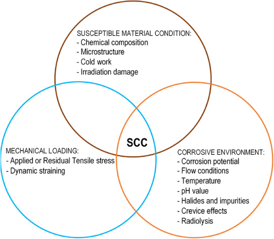
The presence of SCC is due to a distinct interplay of three pivotal factors: extended tensile stress or strain, an aggressive electrolyte, and susceptible material conditions as shown Fig. 1. Susceptibility of ASS typically refers to their vulnerability or sensitivity to certain type of damage and is a function of several factors such as metallurgical conditions, degree of sensitivity, etc. Followed by internal or external sources, chloride rich salt can come into contact with metal surfaces. When these metal surfaces (ex: nuclear storage canister) cool down enough, the salts may absorb moisture from the air, creating a potentially corrosive layer of chloride-rich salty liquid on the metal's surface. This localized aqueous brine layer can lead to corrosion. In order to initiate the crack depends on the degree of applied or residual stress intensity. The variation of stress intensity is based material behaviour and loading conditions [[21], [22], [23], [24], [25], [26], [27], [28], [29], [30]].
 Fig. 1. Requirements for SCC [31,32].
For the corrosion inspection, traditional NDT such as X-radiography, ultrasonic, eddy current testing, magnetic particle inspection, and liquid penetration techniques are not effective in detecting cracking, pitting, and crevice corrosion. Most of these approaches are performed offline when the components are steady state [18]. Conventional NDT transient methods for online corrosion monitoring have been used in facilities to reduce economic losses and safety concerns over the past three decades [11,33]. For any sector, detecting SCC is a critical issue. To predict this effect, AE is a unique and real-time promising technique that plays a significant role in the detection and monitoring of corrosion [[34], [35], [36], [37], [38], [39]]. More to say about, the AET is a tremendous prospective characterization technique for fracture mechanism evaluation on metallic specimen testing [40].
AET is a non-intrusive and passive methodology integrated with automated data collection equipment, employed for continuous monitoring and damage prediction [41]. It relies on the propagation of transient elastic waves, generated by rapid energy release within a material. During operational and online phases, AET can detect tiny flaws within structural materials, as well as tracking the onset and progression of SCC, pitting, and crevice corrosion. However, elastic waves are mechanical vibrations that travel through a material without causing permanent deformation. The observation of wave characteristics like wave propagation, attenuation (decrease in wave amplitude as it travels through a material) and velocity are used to understand the internal structure and integrity of materials by analysing how these waves interact with the material's properties [42]. In stress intensity analysis, the Kaiser Effect reveals itself through the observation of AE signals. This phenomenon becomes evident when a material undergoes loading and unloading cycles, indicating a shift in its stress state [43]. The Kaiser Effect frequently serves as a stability indicator for materials and structures. Notably, Fowler introduced the Felicity ratio based on the Kaiser Effect, presenting a quantitative approach to assess the deterioration of structures [44]. This comprehensive exploration of elastic wave traits and their interactions contributes to a more nuanced understanding of material behaviour and its significance in evaluating structural integrity.
AE sensors play a vital role in monitoring SCC during testing, establishing a direct connection between findings and AE signals. This correlation aided in estimating SCC initiation and propagation rates [45]. Effective AE monitoring for SCC necessitates precise AE sensor calibration. This involves setting threshold amplitudes and optimizing pre-amplifier values. Additionally, adjusting low and high filter frequencies are crucial to eliminate mechanical and electromagnetic noise. This approach enhances SCC assessment accuracy and bolsters the ability to detect and mitigate corrosion-related issues [46,47].
Many researchers have conducted the experiments on various material grades of ASS with appropriate methods [48]. In accordance with testing procedures outlined by industrial standards such as ASTM C692, API 939-D, and NACE TM0177, among others, AE technology is utilized for the testing and evaluation of SCC damage mechanisms in pressure vessels, pipes, and structures. However, the characteristics of AE signals and their association with SCC damage remains a subject of controversy.
SCC can lead to sudden structural failures, especially in thermally insulated components. This poses a significant challenge in nuclear industries, demanding accurate prediction and loss prevention. Hence, the impetus behind this study is to employ AET to detect and assess SCC susceptibility, varying interacting parameters within CI-SCC tests. The significance of this study enhances understanding of SCC mechanisms, contributing to secure operational limits and potential detection innovations for safer practices and reliable operations. In this review, studied AE signal correlation to CI-SCC damage on ASS materials in various stages. It introduces ASS, CI-SCC mechanism, and AE parameters. The review covers SCC monitoring and detection through AET. Recent developments under varying test parameters are discussed, highlighting mechanisms.
2. Austenitic stainless steels
Babakov 1961, stated that the addition of nitrogen to steels containing 18 %, 20 %, and 22 % chromium leads to the formation of pure austenite with a more considerable proportion of nickel (up to 6 %) [49]. ASS are an extraordinary family of stainless steel that has been used in residential, industrial, transportation, and architectural items for a variety of reasons, including corrosion resistance, formability, strength, and characteristics at elevated temperatures [50]. While using in various operations, generation and propagation of cracks, movement of dislocations and grain boundaries, creation and growth of twins, fracture and de-cohesion of brittle inclusions, phase transitions, and so on are some of the different causes that have been occurred in metals [51].
In ASS, the chromium element is the one that provides the passive film with its stability. The difference in potential between the metal and the solution, temperature, acidity, and halide content are the main variables that impact film stability [52]. Halides such as chlorides (Cl−), bromides (Br−), iodides (I−), and fluorides (F−) are susceptible to pitting corrosion except for fluorides because it is a weak acid anion and hardly soluble in water also act as an inhibitor in chloride environments against to pitting and crevice corrosion. Whereas chlorides are most soluble in water, followed by bromide and iodide. However, SCC occurs on sensitized stainless steels in all halide solutions [53].
Sensitization occurs when ASS are undergoes heat up between 500 °C and 900 °C and form a chromium-depleted zone along the grain boundary due to the precipitation of chromium carbide [48,54]. The kinetics of this precipitation is affected by carbon percentage; those ASS grades with less than 0.03 % required more time to sensitize [55]. Moreover, chromium and nitrogen augment carbon solubility, leading to the cessation and reduction of precipitation. Conversely, molybdenum and nickel, by reducing carbon solubility, promote precipitation. At this juncture, nitrogen levels introduce a delay in carbide precipitation [56]. However, the elements that enhance passive film stability are resistance to pitting, crevice corrosion, and SCC [57].
The chemical compositions of frequently used ASS in industries are shown in Table 1 [[58], [59], [60]]. Along with its outstanding comprehensive characteristics, such as anti-corrosion, good toughness, and heat resistance, SS304 and 316 steels have become widely utilized in industry to make different containers and corrosion-resistant parts. The types SS304 and SS316 are extensively utilized for pressure boundary piping in BWR (Boiling Water Reactors) and for primary circuits in PWR (Pressurized Water Reactors). Furthermore, SS316 materials with add-on chemical elements such as titanium (Ti) and slightly changes in Si and P are employed for fuel cladding tubes in light water reactors such as sodium-cooled fast reactors [20,61]. They have such excellent mechanical properties such as Tensile strength (691 MPa), Yield strength (410 MPa) and Elongation 66.5 % [37].
Table 1. Chemical compositions of frequently used ASS for piping and cooling systems.
| Alloy element (wt.%) | C | N | Si | Mo | Mn | P | S | Ni | Cr | Others |
|---|---|---|---|---|---|---|---|---|---|---|
| SS304 | 0.06 | 0.10 | 0.35 | – | 1.65 | 0.029 | 0.004 | 8.13 | 18.23 | – |
| SS316 | 0.08 | 0.10 | 0.75 | 2.00 | 2.00 | 0.045 | 0.030 | 10.00 | 18.00 | – |
| SS321 | 0.08 | 0.10 | 0.75 | – | 2.00 | 0.045 | 0.030 | 9.00 | 17.00 | Ti 0.70 |
| SS347 | 0.08 | – | 0.75 | – | 2.00 | 0.045 | 0.030 | 9.00 | 17.00 | Nb1.00 |
| SS310 | 0.25 | – | 1.50 | – | 2.00 | 0.045 | 0.030 | 19.00 | 24.00 | – |
| SS302 | 0.15 | 0.10 | 0.75 | – | 2.00 | 0.045 | 0.030 | 8.00 | 17.00 | – |
The passive layer of ≤18 % Cr in ASS provides corrosion resistance. The passive film formation happens with adsorption of OH− ions followed by chromium combined with oxygen or by OH− ions direct discharge [62]; it forms a thin layer that does not spall away [63]. If scratches occur or the development of soluble compounds on the metal surface, the passive layer has been ruptured and forms again instantly if there is enough chromium existent, if pitting does not start [64].
One of the reasons pitting corrosion is so dangerous is that once a pit formed by the passive film collapses into small, isolated spots [65]. It has a strong tendency to expand even if the bulk of the surrounding steel is still intact. The resistance to pitting depends on the alloy elements referred to as PREN (pitting resistance equivalent number) [66]. The PREN is to estimate the expected pitting resistance in a chloride-containing environment. The empirical formula of PREN is %Cr + 3.3 x %Mo + 16 x %N, where the amounts of chromium (Cr), molybdenum (Mo), and nitrogen (N) in the alloy are represented as percentages of weight. A higher PREN value is more corrosion resistant the steel, e.g., SS316 (PREN = 25) has better pitting resistance than SS304 (PREN = 20) in a chloride environment because SS316 contains molybdenum (Mo) which can improve the pitting resistance, but 304 is widely used because of low cost than type SS316 [67,68]. And the other grades of ASS, such as SS310, and SS321/SS347, have been used for reducing the cold work hardening rate, resistance to elevated temperature, welding, and excited temperature applications [69,70]. Nowadays, designers should be especially cautious of pipe and tubing, which frequently has high sulfur levels, to facilitate tube welding at the expense of corrosion resistance. For example, 316 tubing with 0.015 % sulfur has no better pitting resistance than 304 tubing with less than 0.003 % sulfur [52].
The likelihood of pitting corrosion increases if chloride ions raise and compete with OH͞ (O2 H2O) for surface adsorption on oxide spots and compounds formed with excessive solubility, resulting in a passive film becoming very thin. The passive film ruptures from the development of adsorbed ions, which accelerates the area extent and the development of internal stress at the interface. Pitting corrosion develops rapidly in a chloride environment, as shown in Fig. 2. It has two parts: anode zone and cathode zone. The deep structure of material where pitting occurs is referred as an anode area. The cathode zone forms on the diffused interface, which is a recapture for electron and produces the pitting direction and dominates this anodic area. The passive film becomes more distorted and disruptive when exposed to a chloride aqueous solution [71] then instantly formed chromium enriched passive film. The passive film thickness grows due to Fe2+ raise in oxide at elevated temperatures and in prolonged exposure time. The concentration of chloride ions, however, promotes pitting corrosion in the usual atmospheric range of humidity [72].
 Fig. 2. Pitting corrosion growth mechanism [71].
3. Chloride induced stress corrosion cracking (CI-SCC)
Corrosion, when combined with tensile stress, can lead to SCC and this is unique to a susceptible metal in a particular environment [73]. In the SCC systems, transient oxidation can adopt multiple kinetic laws depending on the material/environment/loading circumstances. The increase of crack tip oxidation can be achieved by either physical degradation, physical-chemical degradation modes, or both [74]. Shallow pits are easy to inspect and are improbable to affect the component's structural integrity. They have the potential to function as stress concentrators, causing SCC [75]. The occurrences of corrosion and/or SCC found in nuclear, petroleum, and other manufacturing industries under various corrosive environments such as molten chlorides, caustics, ammonia, amines, and polythionic acids. Chlorides are the most common cause of SCC in ASS and nickel alloys as in transgranular mode, whereas intergranular crack usually occurs in sensitized steels [76,77].
The phenomenon of CI-SCC on ASS is based on various environmental factors and parameters [78,79]. The chloride content, pH, and temperature are the main parameters contributing to CI-SCC susceptibility. Scharfstein and Brindley discussed that ASS are vulnerable to chloride SCC in corrosive solutions if the temperature is as low as 165o F (74 °C) to 200o F (93 °C). However, the circumstances that lead to cracking are unique [80]. Rain, coastal fog, deicing salt, wash water, fire and deluge system testing, and process leaks or spills are examples of external sources of chlorides that fall on the metal surface. Probably the source of chlorides is either from thermal insulation or from external sources or both because most nuclear and petrochemical industries are located near the coastal areas. The degree of environmental effect and improper maintenance failures (SCC) induced by introducing chlorides from external sources and thermal insulation are likely to develop. The majority of CI-SCC failures are caused by these sources. Although localized corrosion is generally recognized to be the cause of CI-SCC but the propagation of crack mechanism is still intricate and not completely unstated [81,82]. The majority of authors concur that crack propagation comprises the combination of metal dissolving over a highly localized area (electrochemistry) and atomic level mechanisms that fracture the metal structure [83,84]. The potential CI-SCC mechanisms are as follows.
3.1. SCC mechanism
The SCC mechanism was broadly categorized as dissolution-based and cleavage-based mechanisms [48], established through extensive research on corrosion processes. Dissolution-based SCC results from gradual material dissolution in corrosive environments, initiating cracks [85]. On the other hand, cleavage-based SCC is characterized by the brittle fracture along grain boundaries [86]. Comprehending these mechanisms is vital for evaluating the susceptibility of materials in various industries. Extensive research has revealed the factors that influence each type of SCC, thereby guiding the development of mitigation strategies and the selection of corrosion-resistant materials to prevent catastrophic failures.
3.1.1. Dissolution mechanism
The dissolution-based process involves localized preferential corrosion at the crack tip, while the remaining portion stays in passive state. The rate of dissolution depends on the selected test parameters. The dissolution-based mechanism can be classified into: (a) Pre-existing active path model, (b) Strain-generating active path mechanism (film rupture model and slip step dissolution), and (c) Corrosion tunnel model as shown schematically in Fig. 3[48,86].
 Fig. 3. Schematic view of dissolution mechanisms: (a) Pre-existing active path mechanism [91], (b) Strain generating active path mechanism: (b–i) Film ruptured model, (b-ii) Slip step dissolution, (c) Corrosion tunnel model.
For (a) Pre-existing active path mechanism, the pre-existing grain boundaries are susceptible to anodic dissolution or SCC by the formation of intermetallic and segregated compounds. In these circumstances the tensile stress plays a significant role in preserving crack susceptibility at the crack tip and accelerates the dissolution. This is also called mechanoelectric effect. The affected area adjacent to chromium depleted grain boundary will be preferentially attacked as intergranular cracks as shown in Fig. 3(a). For example, the material can exhibit an active dissolution path along the grain boundaries in case of sensitized ASS [57,83].
For (b) Strain-generating active path mechanism, two distinct models were established to describe the crack growth based on active cycles of dissolution and passivation at crack tip or slip step, as shown in Fig. 3(b), as follows:
(b-i) Film rupture dissolution model: The film rupture SCC mechanism was well established for metals or alloys with a strained passive layer on the surface. In this mechanism, crack growth describes a sequence of rupture-dissolution-passivation. Each step must begin with a considerable potential for rupture in order to maintain the crack growth. Such steps are illustrated in Fig. 3(b–i). The localized plastic strain causes rupture of the passive film, and then the bare metal is exposed to the environment and dissolves according to the rate of film rupture [48,87].
(b-ii) Slip step dissolution model: This model is similar to the film rupture model as if the metal species promotes the passivation than the dissolution rate. As result crack growth disrupted periodically by the appearance of slip steps, and the naked slip-step continues to dissolve until the next re-passivation as shown in Fig. 3(b-ii). When the passive layer covered the slip steps, the dissolution movement stopped, forming arrest marks on the cracked surfaces. On the actively cracked surface where film rupture occurs continuously, the surface is smooth without any distinctive features and can exhibit cleavage, while arrest marks are recognized for transgranular cracks. On the other hand, the presence of grain boundary features on the cracked surface would cause intergranular cracks [88,89].
For (c) Corrosion tunnel model, the crack is initiated by the formation of corrosion tunnels where the dissolution and mechanical fracture have coexisted. The corrosion tunnels formed at the emerging slip steps and grow gradually with their diameter (seems to elliptical) and length by the application of tensile stress and lead to a mechanical failure or ductile fracture as shown in Fig. 3(c). Consequently, the morphology of corrosion tunnels into thin and flat sections and breaks mechanically. These corrosion flat sections approach atomic dimensions, and it is expected that the matching surfaces will be perfectly correlated [14,48,90].
In the dissolution-based model, the crack growth rate depends on the rate of repassivation (ROR) and rate of dissolution (ROD). If the ROD is more than ROR, crack growth will be fast because crack tips are free from the passive layer by the anodic solution (Cl−) and mechanical loading. If the ROR is more than ROD, many stoppages occur in the crack path because film dissolution and repassivation occur simultaneously on the naked metal surface shown in Fig. 4(a–d). In this process, when the thickness of the passive film has increased, the repassivation takes place then the crack begins to expand in slip steps by slip oxidation [[92], [93], [94]]. At the developing slip steps, a fine array of miniature corrosion tunnels develops by the dissloution and mechanical cracks have been combined. The schematic view of developed tunnel model as shown in Fig. 4(c–e). At the damaged ligaments, this type of model shows a grooved fracture surface with indications of microvoid coalescence. To accomplish, according to the tunnel hypothesis, tunnel shaped pitting is generated when a sliding band interacts with a passive layer, which expands sideways under mechanical stress and eventually produces a feathered cracks as shown in Fig. 4(f).
 Fig. 4. Mechanism of passive film rupture for SCC [92].
3.1.2. Cleavage mechanism
Cleavage-based mechanism is a crystal breaking process by propagating a crack or fissure over a crystallographic surface, or atomic bond rupture in molecular system indicative of a brittle failure. I t can be subcategorized into: (a) Adsorption induced cleavage, (b) Tarnish rupture, (c) Film induced and (d) Atomic surface mobility as shown in Fig. 5 [48,86].
-
(a)
Adsorption induced cleavage mechanism: This mechanism involves the adsorption of certain environmental species, with stress being required for cleavage fracture. The mechanical load (tensile stress) plays a vital role in disrupting interatomic bonding or decohesion along the grain boundary. The strained interatomic bonds at the crack tips are weakened by the presence of adsorbed ions, as shown in Fig. 5(a). In this progression, various adsorbed species such as chloride ions, hydrogen, and metal atoms are all significant contributors [95].
-
(b)
Tarnish rupture mechanism: This mechanism describes the repetition process of film fracture –crack growth-film formation-arrest marks. The brittle passive film under the action of tensile stress, allows a crack into the material, where it encounters a tough, ductile matrix resulting in blunting. When the blunted crack tip is exposed to the solution, re-passivation occurs, promoting to stop the crack propagation and formation of arrest marks, as shown in Fig. 5(b). In accordance, when a new layer of brittle film forms earlier the crack tip, the crack will continue to propagate in a stable manner. In this mechanism, the predominant nature of fracture surface is transgranular, but later the theory was modified to account for intergranular SCC based on the penetration of passive film along the grain boundaries earlier the crack tip. In this scenario, the crack growth consists of alternating phases of arrest marks due to film growth and brittle-film fracture [96,97].
-
(c)
Film induced mechanism: This mechanism is an updated model of tarnish mechanism. In the film-induced mechanism, the assumption is that the formation of a passive film due to dissolution causes brittle cracks by applying tensile load. These cracks spread over distances considerably greater than the film thickness then adjacently moved into the metal volume as shown in Fig. 5(c) [98]. Due to the tough matrix of the metal, crack propagation has been stopped and formed blunted cracks by plastic deformation until the crack movement is repeated. Once crack propagated, it rapidly penetrated a small distance into underlying ductile metal matrix. The degree of coherency and bonding between the passive film and metal matrix, the substrate's fracture toughness, film thickness, and the initial velocity of the cleavage crack may all influence the extent of the additional film-induced cleavage component of crack advance [99].
-
(d)
Atomic surface mobility mechanism: This mechanism well possibly predicts the SCC susceptibility, impact of environment on SCC, and the effect of hydrogen atoms on crack propagation [100]. The updated mechanism stated that the vacancy diffusivity plays a key role in the process of crack movement. At the onset of this process, crystal lattice elements within the corrosive solution are removed in the vicinity of the crack tip, resulting in the formation of vacancies. These vacancies captured by stressed lattice towards the crack region (low stress region). As a result of tensile stress, the crack propagates by an atomic distance, as shown in Fig. 5(d) [101]. In this mechanism, the surface mobility may possibly act at the crack region where the presence of contaminants in the aqueous solution.
 Fig. 5. Schematic view of cleavage mechanisms: (a) adsorption induced [95], (b) tarnish rupture [96], (c) film induced [102], (d) atomic surface mobility [100].
The various proposed SCC mechanisms differ from one another, but some of the mechanasim have a marginal difference to each other in the dissolution-based models. Also, some of the models have a limited evidence to support its mechanism. Chattergee [48] stated that, multiple mechnaism are plays in the crack region instead of a particular mechanism and there is no single mechanism plays a role solely in one system. For example, in the cleavage based model, hydrogem atoms diffuse the crack tip and embrittle the metal leads to SCC. At the crack tip hydrogen evaluated cathodically to initiate the crack and its extension. On other side anodic chloride ions dissolves oxide film and migrate into the pit. The formation of anodic oxidation increases the acidic ions at the crack tip. At the crack tip, cathodic and anodic reactions are not feasible. However, anions and cations produced by negatively charged Cl͞ and OH͞ ions migrate towards the crack tip during anodic metal dissolution (slip dissolution or film rupture mechanism). In addition, H+ ions are associated with metal hydrolysis [103].
3.2. SCC development and sensitization effect
The observation of crack growth rate depends on load conditions, corrosive environmental conditions, and exposure time. The crack growth rate is equal to the length of the crack by exposure time and metal sensitization. Sensitization is a loss of integrity or corrosion resistance of the material which susceptible to intergranular corrosion. In this process, chromium and carbon form a chromium carbide and precipitate along the grain boundaries. As a result, chromium becomes depleted in the vicinity of grain boundary as shown in Fig. 6. Also, the protective film abruptly becomes discontinuous when the chromium content decreases [104]. While the ASS is sensitized by heat treatment, the SCC resistance has been decreased and the crack development accelerates even at low-stress intensities [105]. For example, the path of the crack in an anodic solution as illustrated in Fig. 7, represented a specific type of crack. IGSCC (intergranular stress corrosion cracking) occurs when applied or residual stress is present in sensitized steels, leading to crack propagation along the grain boundaries. The intergranular cracks may be longer and deeper than unsensitized steels depending on the degree of sensitization. The unsensitized stainless steels occur predominantly TGSCC (transgranular stress corrosion cracking) and the crack path moves across the grain boundary with branches [106].
 Fig. 6. Precipitation of chromium carbide ((Fe, Cr)23 C6) at the grain boundaries in stainless steel during sensitization [104].
 Fig. 7. Mechanism of common SCC by anodic solution with TGSCC and IGSCC [92].
In the nuclear reactor plants, components made of ASS in both PWR and BWR are potentially susceptible to two significant forms of SCC: IGSCC and IASCC (irradiation assisted SCC). IGSCC tends to occur in thermally sensitized ASS components, especially in BWR. IASCC occurs by neutron fluence exposure and characterized by IGSCC initiation and propagation [107]. TGSCC typically initiates on the external surface of ASS components. These forms are facilitated by the accumulation of chloride contaminants, often caused by wetting or water ingress or from thermal insulation, thereby creating an aqueous environment conducive to crack propagation. Such cracks are frequently accompanied by instances of pitting or crevice corrosion, particularly in the presence of tensile stress [108].
When appropriate corrosive environmental conditions are present, ASS can experience failures, leading to the development of SCC. In SCC development, Parkins observed the stress corrosion spectrum in dissimilar materials under different corrosive solutions and was divided into three stages; pre-existing, strain-induced active paths, and specific adsorption at subcritical stress locations [109]. According to the Parkins model, as shown in Fig. 8, SCC development was divided into three stages such as film rupture and pitting, SCC initiation, and propagation [110]. Pitting is associated with the breakdown of localized passive film under the combined action of corrosive solution and applied tensile stress at an elevated temperature. The pit growth gradually increases based on the localized concentration of stress level, leading to crack initiation. The mechanical loading is the essential factor in the crack transition and gives a short or long crack according to the material characteristics. The fractured specimen's characterization can be evaluated by the relationship between the stress intensity factor and time to failure.
 Fig. 8. Schematic diagram of a three-stage model for SCC progression [110].
Hanninen [86] stated that, CI-SCC does not occur in non-sensitized ASS below 50 °C near-neutral solutions, although it can occur at ambient temperature under aggressive low pH circumstances. In chloride solutions, crack initiation was caused by localized corrosion or pitting, and crevice corrosion processes produce acidification at the crack tip owing to hydrolysis of dissolved metal ions in the presence of acidic anions [97,111]. The cracking resistance can be measured by the parameter of time to failure (Tf = Ti + Tp), which equals the components of time for crack initiation (Ti) and time for fracture propagation(Tp) [48].
Xie et al. [112] meticulously replicated PWR conditions and examined SCC phenomena in SS316 steel specimens with different processing methods: cold working and solution treatment. Slow strain rate testing (SSRT) was conducted in a simulated PWR environment with controlled concentrations of boric acid, lithium hydroxide, sodium chloride, and dissolved oxygen, along with elevated temperature and pressure. Results showed that cold-worked steel was more susceptible to SCC, with both types of steel affected by the introduction of chloride ions into the simulated primary water. The mechanism revealed a cyclic process of oxide film rupture and regeneration, driven by metal atom diffusion. The film formation and dissolution process can allow the chloride ions and combine with cations then produced dissolved chlorides. The soluble chlorides develop to form micro-cracks and accelerate TGSCC initiation and propagation. Interestingly, the dissolved oxygen induces the anions diffusion at crack tip and enhances crack growth of cold worked SS316 stainless steels.
After initiation, CI-SCC in ASS cannot be halted but can be mitigated to prevent further growth. A recent study by Yeom et al. [113] focused on a mitigation approach employing cold spray technology for nuclear fuel storage canisters. In this investigation, SS304L powder particles were propelled using nitrogen and helium gases to augment their velocity. The particles formed an adherent deposit by breaking the oxide layer and applied elevated level of compressive residual stress on the material substrate. As this method sealed the crack openings thereby acting as a physical barrier mitigating further growth of CI-SCC. The potential of this technology to offer prompt repair of CI-SCC is significant.
Overall, SCC is a catastrophic failure under certain environmental conditions, particularly in a chloride corrosive atmosphere at elevated temperatures. At a particular temperature, when materials are sensitized in the case of welding or any high temperature applications, the crack occurs along the grain boundary in intergranular mode; else cracks occurs mostly in transgranular mode. The multiple stages of the crack mechanism can be explained based on the Parkins's stress corrosion spectrum and analyzing a dissolution based model under various chloride concentrations. This analysis helps in understanding how chloride ions induce the breakdown of the passive layer and how the crack propagates.
4. Acoustic emission testing
4.1. AE principle and its basic channel
AE is a process in which sound (acoustic wave) is produced because of stored strain energy. It is released by the deformation or fracture of sensible material under stress detected by a surface-mounted AE sensor (vibration to electrical signal conversion device) [114]. The fast release of energy from discrete sources causes transient elastic waves to form inside a material. This results in a successive emission of brief impulsive energy packets, causing redistribution within a system. The emitted energy travels as a spherical wavefront that may be picked up from the surface of a material using sensitive transducers, which are electro-mechanical and positioned on the material's surface [51]. As shown in Fig. 9, the wave transforms into an electrical signal. Proper processing and analysis can provide significant information about the energy source released from the active crack.
 Fig. 9. Schematic view of transient elastic waves detection by AE sensor [114].
A typical AE testing equipment includes a sensor, preamplifier, data acquisition system, and computer for data visualization, as shown in Fig. 10. It indicates the sound wave travelling from the active crack on a material as recognized by AE sensor and transformed to an electric signal derived from AE measurements. In most cases, the amount is a voltage value [mV]. The AE system detection is based on the piezoelectric sensor and its frequency range. Typically, piezoceramics and piezoelectric sensors have wideband and resonant frequency transducers to convert noise displacement to voltage. After the voltage signal has been amplified, it can be stored or inspected. Usually, AE signals are represented as an oscillating voltage that rapidly rises to a peak level while gradually falling to baseline noise levels [41].
 Fig. 10. Schematic view of typical AE channel.
Under specific test circumstances, piezoelectric transducers have been employed on the inspected component's surface to collect real-time data [115]. With each detected impact, hit data is captured and stored whenever an AE signal surpasses the predefined threshold during the data acquisition process. This recorded information encompasses details regarding the moment of detection, AE signal characteristics including Amplitude, Energy, and Duration, as well as parametric information present at the time of detection. In time-driven data, the recorded parameters may include predetermined intervals, such as time of measurement, parametric values, RMS (Root Mean Square), ASL (Average Signal Level), and Absolute Energy. The Analog-to-Digital Converter digitizes the hit information, facilitating the display of waveforms associated with each detected hit as another type of captured data [116].
Furthermore, the waveguide, a rod-like metal component, serves as an option when direct connection of the sensor to the structure is not feasible. It is important to highlight that the utilization of waveguide contributes to the increased complexity of the frequency characteristics of AE waves [44]. As depicted in Fig. 11, the waveguide has the option of either being permanently welded to the surface or temporarily positioned, like a sensor installation. The propagating AE wave undergoes attenuation or mode conversion through specific waveguide geometries and materials. This phenomenon is illustrated by the alteration of the AE wave's behavior due to interactions with the waveguide [114].
 Fig. 11. Typical test layout with waveguide and allocation of sensor.
Yan et al. [117] used platinum wire and wedge-shaped brass as a waveguide and welded onto the test piece for transferring the AE signals to a piezoelectric AE sensor. Waveguides have been used on different structures in various environmental conditions where the AE probe is not suitable to place over the test area. The test area may be in corrosive solutions or at elevated temperatures or irregular surfaces. Aluminium or stainless steel has been utilized as a waveguide because of their high sound wave velocity, however the AE signal attenuation should be observed frequently while doing the test.
4.2. AE wave parameters
The transient elastic waves acts as the AE test parameters and the waveform geometry depends on the dynamic sources of amplitude, energy, and material structure which can originate from either micro or macro cracks with time variances. However, the waveform can be divided into two types such as continuous or longitudinal and burst or transverse waveform [118]. Burst AE waveform is a qualitative representation of distinct signal and it resembles a damped oscillation. The continuous waveform is a sustained signal, it appears to be a series of overlapping individual bursts [119]. Typical burst AE waveform as shown in Fig. 12, as AE hit exceeds a specific voltage of AE signal threshold whereas the damage occurred. For every AE hit, each AE parameter is retrieved and sent to the computer [120]. A multi-channel AE measurement system locates the AE source in one, two, or three dimensions based on the arrival time difference across channels, and each AE hit data comprises the arrival time.