Highlights
-
•
The Piezoelectric Wind Energy Harvester, materials, types, and applications are reviewed.
-
•
The Comparison of different Piezoelectric Wind Energy Harvester types are presented.
-
•
Potential advancements and future recommendations of Piezoelectric Wind Energy Harvesting technology are discussed.
Abstract
This paper highlights the advancement in wind energy harvesting using piezoelectric materials to produce sustainable power generation. It is a highly encouraging, fascinating, and challenging method to capture energy from piezoelectric materials. The purpose of this research is to evaluate the principal characteristic groups that affect energy harvesting performance and to provide recommendations for further improvement. Piezoelectric energy harvesters(PEH) can provide electricity for low-power electronic devices, which additionally possess the potential to boost self-powered, autonomous devices. The objective of this article is to provide recommendations for wind energy harvester modeling techniques. After establishing the fundamental idea of Piezoelectric Wind Energy Harvesters (PWEHs), it is next examined how well these devices function structurally and where their research stands in relation to various phenomena, including vortex-induced vibration, flutter, and galloping. A cantilever beamconnected with a tip body is the typical component of a galloping piezoelectric harvester for wind energy collection. Wind energy has been turned into mechanical vibrations and ultimately into electrical power via the flutter phenomena. Fluttering-based wind energy harvesters are a new technology that provides an effective replacement for conventional wind turbines. The future development trend for PWEHs has been anticipated. The most current developments in strategies and approaches for wind energy harvesting using piezoelectric materials are also discussed in this paper. First, this paper highlights various piezoelectric energy harvesting materials, then it shows various wind energy harvesters’ design. After that this paper displays various types of wind energy harvesters and their applications. Finally, it highlights some challenges, future development, and recommendations.
Keywords
Wind energy harvesters
Piezoelectric materials
Energy harvesting
Wind flow
Sustainable power generation
Energy conversion
Nomenclature
- Piezoelectric Wind Energy Harvesters
-
PWEHs
- Piezoelectric Energy Harvester
-
PEH
- Micro electromechanical systems
-
MEMS
- Wireless Sensor Nodes
-
WSNs
- Energy harvesting
-
EH
- Lead zirconate titanate
-
PZT
- Fe-doped reduced graphene oxide/poly (vinylidene fluoride)
-
Fe-RGO/PVDF
- Vortex-induced vibration
-
VIV
- Structural health monitoring
-
SHM
- Piezoelectric nano-generators
-
PENGs
- Multilayer Perceptron Artificial Neural Network
-
MLP ANN
- Photo Voltic
-
PV
- Macro Fiber Composite
- Poly (vinylidene fluoride and trifluoro ethylene)
-
P(VDF-TrFE)
- Barium titanate
-
BT
- Bismuth sodium titanate
-
BNaT
- Sodium potassium niobate
-
KNN
- Zinc oxide
-
ZnO
- Wind-induced vibration
- Transverse galloping
-
TG
- Flow Induced Vibrations
- Turbulence Induced Vibrations
-
TIV
- Waterproof Hybrid Wind Energy Harvester
-
WP-HWH
- Limit cycle oscillations
-
LCOs
- Unmanned aerial vehicles
- Flutter based wind energy harvesters
-
FEHs
1. Introduction
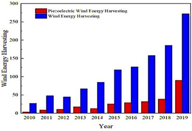
A type of fresh, renewable energy frequently used to preserve the environment is wind energy. A significant domain of research in self-powered generation is the utilization as well as the transformation of wind energy [1]. There is a lot of easily attainable wind potential. Since the world's viable fossil energy supplies are quickly running out, sustainable renewable energy supplies have recently gained popularity [2]. Over the years, we have seen a lot of interest in piezoelectric energy harvesters. Energy harvesters are a possible replacement for power sources because they have a limited lifespan and require expensive maintenance since they can produce sustained power [3]. MEMS (micro electromechanical systems) and WSNs (wireless sensor networks) are two examples of self-powered systems that benefit significantly from the use of piezoelectric energy harvesters [4]. An instrument known as a piezoelectric energy harvester produces energy by harnessing the energy that the outside environment exerts on the piezoelectric components [5]. This technique is used to convert surplus energy into useable power for electrical purposes. The direct piezoelectric effect acts as an organizing principle for the piezoelectric energy harvester's mechanics [6]. Fig. 1 [7] displays the graph of number of publications relating to wind energy harvesters and PWEHs that were submitted to the Web of Science during the previous ten years.
 Fig. 1
Piezoelectric materials are desirable for application in detectors, actuators, energy harvesting (EH) equipment, and several other applications because they can directly transduce electrical and mechanical energy [8]. Typically, a unique mechanical framework converts wind energy initially into resonance energy, which is subsequently converted into electrical energy. Electromagnetic, electrostatic, and piezoelectric kinds are the basic methods of resonance energy conversion to electric energy [9]. When subjected to foreign deformity, piezoelectric materials can generate electricity, offering potential power densities associated with embedded systems [10]. The efficiency of piezoelectric material in converting electrical energy to mechanical energy and the other way around is measured by the electromechanical coupling factor, [11]. In recognition of its substantial coupling coefficient and thus higher energy generation compared to various piezoelectric materials [12], lead zirconatetitanate (PZT) currently occupies the position of the most well-studied ceramic-type piezoelectric material. Jacques and Pierre Curie discovered piezoelectricity in inorganic crystals for the first time in 1880 [13]. The materials' intrinsic and extrinsic properties produce the piezoelectric effect. The former is consistent with the ferroelectric crystal structures being preserved by the relative anion/cation change [14]. The latter results from the mobility of the domain wall. To achieve the appropriate characteristics for use in practical situations, the PZT materials are additionally doped with other materials, such as Mn, La, Sr, Fe, and Cu [15]. Since the bulk of piezoelectric materials utilized in real-life situations today are inorganic in nature the phenomenon is still mostly linked with ceramic materials [16]. There are various piezoelectric energy harvesting technologies as well [17]. Karan et al. in his article [18] delves into the remarkable self-repairing abilities exhibited by piezoelectric bipyrazole organic crystals. These crystals possess the unique capability to spontaneously recombine after mechanical fracturing, undergoing autonomous self-healing within milliseconds and reinstating their structure with crystallographic accuracy. Similarly, there is research showing highly efficient hybrid piezoelectric nanogenerator [19] emphasizing its flexibility, sensitivity, cost-effectiveness, and superior performance in energy harvesting. The piezoelectric energy harvester employed a non-electrically poled Fe-RGO/PVDF nanocomposite film, yielding an impressive open circuit output voltage of 5.1 V and a short circuit current of 0.254 μA through repetitive human finger imparting [20].
All piezoelectric polymers have the following characteristics: The polymer chains include continuous molecular dipoles; The dipoles may be realigned and altered under specific circumstances; the dipole orientation may be maintained after it has been achieved; and the polymer is able to withstand significant mechanical deformation. The commonly used PZT ceramics have lead contamination. Inorganic as well as organic materials can both be designated as lead-free. The very first lead-free piezoelectric ceramics were reported using BT-based ceramics [21].
Another key category of variables that greatly affect the energy harvester's efficiency of output is its structure. Measurements and arrangements must be included in the structure's specifications. The instances of mechanical and electrical qualities are impacted [22]. Highly concentrated piezoelectric materials and persistent magnets with high magnetic field densities have been developed because of recent improvements in nanotechnology. Regarding either permanent magnets or piezoelectric materials, unique configurations may be created in the current environment [23]. Recent advancements in piezo-wind electric generator studies reflect the growing popularity of renewable energy sources [24]. Embedding piezoelectric material or transferring rotational energyto linear power for deformation can both be used for transforming wind energy into electrical energy. The rotational motion can use piezoelectric materials explicitly [25].
Piezoelectric wind-powered harvesters built around flow-induced oscillations are receiving a lot of consideration since they can supply mobile sensor nodes with long-lasting, reliable power [25], wind energy harvesting using piezoelectric materials is also shown in Fig. 3 [63]. The harvester scavenges energy in motion from the wind via vortex-induced vibration (VIV), flutter, galloping [26,27], and wake galloping of structures. Additionally, it has a lot of potential applications in networked wireless sensors. Wind vortex can be analyzed by the spectral element method [28]. The best output power has been explored for energy harvesters depending on both vortex-induced vibration [29,30] and galloping phenomena. To capture wind energy via vortex-induced motion and galloping, an ordinary cantilever beam with piezoelectric sheets connected to it is often built [31]. The consequences of efficient strength, weight, suspension, and external circuits on the output characteristics of the energy harvesting system have been extensively explored to increase the speed of the wind range of VIV-based energy generation [32,33]. The tip body is frequently linked to the unattached end of a cantilever beam that has been clamped at one of its ends and a galloping piezoelectric generator at the other. The aero-elastic property of the extractor and, consequently, the effectiveness of energy harvesting are significantly influenced by the tip body. A cantilever piezoelectric beam coupled to a spherical cylinder was examined as a type of bluff body by Wang et al. [34]. They tested the impact of a plate with a rectangular shape placed downstream of the water's path on the system's output voltage. Additionally, they examined an outstanding performance piezoelectric wind energy generator with Y-shaped clamps and showed that they performed better than the square attachments now in use [35]. In accordance with flutter, which possesses the properties of self-excitation, disparities, nonlinear behavior, massive magnitude, and severe distortion, it is ideal for extremely fast natural wind energy collection. It also has a more powerful resonance response along with more effective harvesting efficiency under substantial wind velocity constraints. Therefore, the difficulties in current research are to create small, highly effective wind energy harvesters in low wind speed situations [36].
Swift developments in wireless technology and low-power gadgets have made it possible to utilize autonomous devices for the surveillance of structural health more often. Among the primary advantages of using wireless structural health monitoring (SHM) [37], systems are that they can offer constant surveillance without worrying about the related setup expenses associated with wiring, and these can be expensive depending on the extent of the sensor network [38]. Modern study has concentrated on creating systems that can be fueled by harvesting atmospheric vitality, such as mechanical vibrations, sun, and the breeze, directly through their vicinity [39]. This is the reason numerous wireless sensor nodes utilize conventional batteries that need to be replenished. The capacity to continually assess the overall state of an aircraft structure is provided by structural health monitoring (SHM), that, when properly implemented, offers several significant benefits [40]. The core of structural health monitoring is piezoelectric materials, which may provide electrical energy in anticipation of structural stress or overload. Different sorts of energies can be used with micro-nano energy harvesting devices with various methods and configurations [41]. Micro energy harvesting encounters several benefits for operating wireless sensors, including a longer lifespan, less maintenance work, and lower costs. The piezoelectric nano-generators (PENGs) exploit the piezoelectric effect to harvest clean power from air, waves, biomechanical motions, and mechanical resonances in nature [42]. Regarding distant applications that are extremely demanding within view of the power they utilize, sustainable sources of energy, like solar panels or wind turbines, may be utilized. Energy harvesters should pay close attention to energy balancing for applications. From research, prospective uses for consumer electronics, industrial machinery, and military purposes have been investigated [43].
There are several articles that lead to the fact that piezoelectric materials cause the reduction of CO2 emission and other techniques of possible clean energy production. Various studies explore different aspects of renewable energy and emissions reduction across several regions. One study utilizes a Multilayer Perceptron Artificial Neural Network (MLP ANN) to forecast CO2 emissions in Middle Eastern Countries [44] and considering energy consumption and GDP [45]. In Iran's southern region, a 230 KW Photo Voltic (PV) system with a vertical tracker could potentially reduce 36 % of total emissions from the existing setup [46]. Another investigation delves into wind powered reverse osmosis plants as a promising option for renewable desalination [47], especially in coastal regions. Additionally, there is a discussion about wind power's potential for desalination in Kuwait [48].
The introduction, fundamentals of the piezoelectric effect, and materials are covered first in this review article [49]. Then, a summary of several character types and attributes is provided along with their influences on design for increased effectiveness [50]. Afterwards this article highlights the current developments in piezoelectric wind energy harvesting devices. Then there are various applications and usage for these energy harvesters [51]. This main goal of this article is to highlight the PWEH's features, applications and limitations, serving as a jumping-off point for further research.
2. Piezoelectric energy harvesting materials
Piezoelectric materials may be divided into two primary groups: hard and soft piezoelectric materials. Yet, because of their high stresses, soft piezoelectric ceramics are favored, whereas hard piezoelectric ceramics' restricted domain wall motion leads to low piezoelectric constants and little hysteresis characteristics [58]. Polymer piezoelectric materials (PVDF) have strong impedance ratings and wear resistance equivalent to water and the human body because their acoustic impedance is like a wide range between piezo-ceramics and water [59]. In addition, polymer composites (PZT) offer high electromechanical coupling, superior depolarization resistance, and low dielectric losses under strong electrical field exposure [60]. The most often utilized piezoelectric materials have the following qualities: flexibility, lightweight, high responsiveness, low-frequency response, and low-frequency operation [61,62]. Low-profile transducers made of these materials include Thunder, Active Fiber Composite, Macro Fiber Composite (MFC), Radial Field Diagram, Quick Pack, and Bimorphs [63].
Due to its mobility, resistance to damage and the effects of the environment, and better efficiency at converting energy, MFC offers several benefits over PZT and bimorph. Yet, MFC may very well enhance an inadequate current, which is unacceptable.
PZT, on the contrary way, is less resistant and more effective, but it is also more brittle [64]. The following efficiency formula was discovered through their numerical study [65].(1)where η is the efficiency, is the voltage drop across , is the force exerted on the plate's base, represents the plate's displacement, is the time interval between data points, is the data point index and is the number of totals acquired data sets [63]. Table 1 contains the data of the efficiency research of 3 various piezoelectric materials at various frequencies.
| Signal |
PZT Efficiency (%) |
MFC Efficiency (%) |
Qp Efficiency (%) |
|---|---|---|---|
| Resonant | 3.56 | 1.182 | 0.4337 |
| 3.47 | 1.66 | 0.5476 | |
| 2.09 | 1.083 | 0.871 | |
| Reference [66] | Reference [67] | Reference [2] | |
|
Chirp 0–500 Hz |
2.153 | 0.3931 | 1.5655 |
| 2.787 | 1.5677 | 1.2511 | |
| 2.0265 | 0.3154 | 1.392 | |
| Reference [68] | Reference [69] | Reference [22] | |
|
Random 0–500 Hz |
3.1954 | 0.7366 | 2.8749 |
| 5.782 | 1.2999 | 1.7553 | |
| 5.7436 | 1.4112 | 2.1234 | |
| Reference [70] | Reference [71] | Reference [63] |
2.1. Categories of materials
2.1.1. Ceramics
PZT, also known as lead zirconate titanate, is the most frequently utilized piezo ceramic. Pb [ZrxTi1x] Lead zirconate titanate, also known as lead zirconium titanate and commonly referred to as PZT, [72]. A ceramic perovskite material has a significant piezoelectric property that causes it to change form whenever an electric field is applied. Ceramics with polycrystalline piezoelectricity Lead zirconate titanate is a substance that is extensively utilized in a variety of industrial applications. The piezoelectric effect is also caused by the inherent and extrinsic properties of the materials [73]. The PZT composites are also mixed with additional elements, such as Mn, La, Sr, Fe, and Cu, to give them the crucial properties needed for practical applications. There are normally just very few PZT series categories available [59]. As compared to several other materials, the PZT performs better. It may be quickly and cheaply manufactured into a variety of bulk, film, or hybrid forms and combinations [74,75] because of its high degree of fabrication. Due to its low loss, PZT—a material with an enhanced natural frequency and a broad bandwidth—can be employed in applications that are both off- and especially on-resonance [52]. Soft (sensor) PZT ceramic powders are widely employed in inflow or level sensors, ultrasonic nondestructive testing, or for thorough inspections of automotive, or aeronautical equipment where strong coupling and/or high charging sensitivities are essential. When extra-power properties are essential, such as for the creation of supersonic as well as enough power in acoustic cleaners, hard (high-power) PZT ceramic powders are utilized [71,76,77], etc. As shown in Fig. 4 [77].
 Fig. 4
2.1.2. Polymers
The essential property of the piezoelectric effect is shared by several polymer families, including polyamides, polysaccharides, and polyesters. A few examples of the various biopolymers exhibiting piezo-electric activity are collagen, cellulose, and silk [31]. Polyvinylidene fluoride, and copolymers constructed of poly (vinylidene fluoride and trifluoro ethylene), are the two most common types of piezoelectric polymers P(VDF-TrFE). Polymers offer stronger mechanical flexibilities, exceptional chemical resistance, and lower piezoelectric coefficientsthan ceramics, which combined minimize wear and extend the life of the device [78]. Ceramics have higher piezoelectric coefficient [79]. PVDF might be used to create sensors, and energy-harvesting devices [80]. Using a Si substrate, the standard MEMS production method was used. A cantilever and solid mass structures are characteristics of the harvester. The piezoelectric layer does indeed have a spin coating that is 1.3 μm thick. The performance of the electrode, which again is due to stammer Al and Ti/Al thin films, was investigated by applying the press and release method. A cantilever with just a contact area of 1200 × 300 μm2 was reported to have a maximum energy output of 35.1 pW, or a power density of 97.5 pW mm2. The low decomposition temperature of the PVDF-TrFE [[81], [82], [83], [84]] materials (160 0C), one of the key benefits of the harvester is that they have greater compatibility with CMOS circuits or wearable electronics than ceramic materials [74]. As per studies, the piezoelectric coefficient (d33) of PVDF-TrFE is 25–40 pCN-1. Hence, piezoelectric energy harvesters based on PVDF-TrFE are honorable contenders to build independent lower-power electronics [85].
A polymer's characteristics are significantly influenced by how it was treated. With piezoelectric polymers, the same is true; in most cases, adequate processing is necessary before any piezoelectric behavior can be noticed. Three recurring processes—heating, stretching, and forming an electric field—are visible when reviewing the data on the creation of piezoelectric polymers [[86], [87], [88]].
2.1.3. Lead-free materials
Due to current environmental concerns, lead-free products are more widely used. PZT ceramics, which are frequently employed, are hazardous to lead. As a result, a lot of researchers focus on discovering substitute materials that satisfy the environmental standards for new usage [89]. Both organic and inorganic substances can be categorized as lead-free substances. Both copolymers and PVDF are organic substances [88]. The family of inorganic lead-free substances known as perovskite, tungsten bronze, and aurivillius may be divided using these criteria (bismuth layer structured ferroelectrics) [90]. The lead-free formulations with perovskite structures under investigation include BT (barium titanate), BNaT (bismuth sodium titanate), KNN (sodium potassium niobate), and its variations. BT-based ceramics have been the initial lead-free piezoelectric materials, and KNN is one of the most important lead-free materials [70,91]
2.1.4. Piezoelectric nanomaterials
In recent years, interest in piezoelectric nanomaterials as well as nanostructures has grown significantly. A classic example of a nanomaterial is zinc oxide (ZnO) [92,93]. It is a plentiful natural metal oxide that is inexpensive, chemically stable when exposed to air, and safe for human physiological use. The hexagonal structural phase of quartzite is the most widespread. Electricity cannot flow through the iron oxide [94,95]. the low-temperature approach can swiftly create the nanostructure on a range of flexible and stiff surfaces without the requirement for poling. Table 1 previously displayed some of the ZnO's piezoelectric characteristics. It is distinct from PZT. Nonetheless, it is simple to create a variety of nanostructures, including nanotubes, and nanorods. Depending on the external forces acting on a structure, DC or AC voltage may be generated [16]. Nano fibers-Based Piezoelectric Energy Harvester is shown in Fig. 5 [55].
 Fig. 5
The capacity to harvest energy by piezoelectric materials has been thoroughly investigated in Table 2.
| Parameter | Inorganic | ||||||||
|---|---|---|---|---|---|---|---|---|---|
| Single Crystal | Bi-Crystal | ||||||||
| Quartz Crystal | PZT - 4 | PZT 5A | PZT - 5H | PZT - 8 | ZnO | AIN | Organic PVDF |
Composite P (VDF-TrFE) |
|
|
K D33 Er Tan Qm v P [ Kg −3] |
0.06 −0.67 4.6 – 100 0.17 2650 [96] |
0.86 −117 32 0.04 475 0.32 7450 [80] |
0.95 −171 50 0.02 75 0.31 7750 -- [97] |
0.2 −267 100 0.03 600 0.34 7450 [98] |
0.8 −97 39 0.007 1000 0.5 75,500 [72] |
- −5 7.9 – 1770 0.36 5600 [99] |
– −5.43 8.5 – 2490 0.25 3260 [100] |
14 −20 12 – 3400 0.33 1700 [35] |
0.25 −25 10–14 0.020 0.018 0.4 1870 [56] |
3. Energy harvester design
3.1. Influence design
The impacting design uses an impulse force and an energy harvester. Umeda et al. give an example as a reference. This is seen in Fig. 6 [104]. The instrument consists of a piezoelectric micro-machined vibrator and a steel ball freely falling, the steel ball collides with the vibrator's inner core. After then, the vibrator reacts dynamically. An output resistor will receive power from the output. A low-frequency oscillation that occurs soon after impact and a high-frequency oscillation that follows makes up the pattern through the load [[101], [102], [103]]. The greatest efficiency was measured at 10 %. Modeling has shown that the efficiency rises with increasing Qm, k, and decreasing tanδ. A little more study has been done on designs, and this will be included in the discussion of impact force later. As will be demonstrated, high-voltage generators are a better fit for the influence design [104].
 Fig. 6
3.2. The design and implemented piezoelectric wind energy harvester
The PWEH design, developed recently (Kurt et al., 2017), consists of four main components, as shown in Fig. 7 [109], and is used to evaluate the efficacy of our control technique. A shaft transmits the movement to the magnetic element in the system's back from the propeller, which may freely revolve at the front due to wind flow [105]. The rear of the device has a three-layer piezoelectric structure that is positioned 120° apart, with a section in charge of managing and conserving electrical power from the piezoelectric layers' terminals. The harvester's three-layered structure results from three distinct piezoelectric layers that, on a circular geometry as illustrated in Fig. 8 [109], have a 120-mechanical-degree phase shift about one another. Small permanent magnets are affixed to layer tips, and their poles are positioned so that they interact with the magnet on the harvester shaft, repel one another, and vibrate the layered tip [106]. According to one of our recent studies, the configuration allows for different magnet numbers at each piezoelectric tip, which helps excite the layers at various frequencies for the best energy conversion [107]. The inherent frequencies of the layers alter as the magnet's mass rises. The shaft is covered with cylindrical polyethylene to prevent any mechanical breaks. It prevents the layers from being destroyed at rapid speeds of wind because variations might cause the layers to be damaged by drawing them stronger into the shaft. In addition, a permanent magnet is positioned beneath the polyethylene well to deflect the piezoelectric magnets [108,109]. The permanent magnet linked to the shaft's center and located just within the polyethylene material spins as when the wind sweeps through all the wings as in the wind tunnel test.
 Fig. 7
 Fig. 8
3.3. Unique designs for enhancing efficiency and making up for deficiencies
Chang et al. (2010) proposed a different method to convert regular DC wind to Alternating by inserting a propeller between airflow and the piezo bimorphs as shown in Fig. 9 [56]. Despite testing being conducted in 3.5 m/s AC wind, the breadth-to-length ratio remained unchanged at 1:5. The use of three blades may have quadrupled the power that the generator produced [49,72,110]. By contrasting it with the speed that was recorded, this frequency was established. Because piezoelectric bimorphs may produce their most power at resonance frequencies, the resonance frequency can be set to the frequency that is accessible from the right side of the bimorph [111].
 Fig. 9
Ting et al. (2010) proposed a nozzle extender to boost the drag force and five-fold wind speed to increase the vibration of the piezoelectric bimorph and maximize energy harvesting as shown in Fig. 10 [56]. The Nozzle Accelerator, which is made up of a flow-guided operation, nozzle, duct, and gated technique that boosts the power on a PVDF cantilever-type mechanism, helped reach the greatest output voltage of 1.313 V [71].
 Fig. 10
Clair et al. (2010) used oscillations induced by self to produce energy. Those who set up a chamber to increase the pressure and as the force and aperture area increased, the beam started to bend. When the aperture widens, the pressure decreases and the motion is redirected by restoring forces [85]. After some time, the bender's back-and-forth motion causes the energy generated and used to balance out, causing the system to experience self-sustaining oscillations. The bandwidth problems can be solved by the idea without the requirement for an additional vibration source, and efficiency is unaffected by design size [64].
3.4. Piezoelectric generator energy maximization and necessary circuit designs
Electric interference is required in energy harvesting devices to guarantee that the voltage applied to energy storage components is suitable. An AC-DC rectifier is perhaps the most widely recognized electrical interface, and the classic interface seen in Fig. 11 [56] is the most often used [56,101].
 Fig. 11
According to Tianze et al. (2009), the transducer's circuit satisfies impedance equalization when the greatest energy may be withdrawn or gained. Additionally, they advised transducers [38,94,107] to use dynamic tuning matching because the resonance frequency varies with peak load, temperature, and moisture. Tan et al. suggested a synchronized charging extracting circuit as shown in Fig. 12[56] with a fly-back transformer for the best energy extraction, and it was discovered that this circuit's maximum efficiency was 63.5 % [56,112]. Experimental and modeling results indicate that a better fly-back transformer may increase the claimed highest efficiency.
 Fig. 12
4. Types of piezoelectric wind energy harvesters
4.1. Wind induced vibrations
A wind-induced vibration is another common design for Piezoelectric Wind Energy Harvesters. The piezoelectric effect operates to transform wind power into oscillation power, which is subsequently collected by this type of harvester. The small PWEH built around wind-induced motion normally doesn't require a rotating framework, therefore it has simple construction and miniaturization properties and is appropriate for the powering of micro-devices [10,112]. As a result, the losses of friction caused by the micro bearing are eliminated. Also, despite a turbine's blade layout, this wind-induced oscillations technique typically converts the flow energy through an arrangement of fluidic uplift and drag [97,113,114]. As a result, wind-induced vibration (WIV) is better suited for low-wind rate operations within the sub-cm scale spectrum. Most crucially, considering an instrument within the cm dimension spectrum, motion on its framework converts to electrical power far more swiftly than the spin [115]. Flutter, vortex induced vibration (VIV), and galloping are the basic mechanisms of wind-induced motion.
4.2. Vortex-induced vibrations
For the first time, Wang et al. modeled, built, and examined a Vortex-Induced Vibration (VIV) power harvester model with electromagnetic induction as shown in Fig. 13 [38]. Shi et al. created consecutive VIV PWEHs in which a cylinder-shaped bluff structure was held up by dual series-connected beams in perpendicular bending paths, while outcomes based on various directions of wind were recorded [95]. VIV-based wind energy harvesting is the most popular harvesting technique, which may create sizeable self-energized oscillation within the lock-in wind speed zone [55,111,116].
 Fig. 13
However, it is only capable of converting wind power into electrical power across a narrow amount of bandwidth, making it unsuitable for future deployment of this harvesting device. Zhao et al. mounted a beam stiffener onto the cantilevered foundation of a vortex-induced vibrational aero-elastic power harvester as shown in Fig. 14 [38]. The results indicated that the electromechanical coupling magnification might extend the lock-in zone of a VIV-based harvester from 1.2 ˷1.9 m/s to 2.5˷3.6 m/s [16]. Vortex excitation is a type of fluid-solid coupling phenomenon that is frequently associated with a bluff body [63]. A cylinder is the most common bluff body form [25]. Vortex shedding occurs shortly after a bluffed body when air passes across it under flow circumstances. When periodic vortex shedding (Carmen Vortex Street) happens on each side of the bluff body's back, an ongoing aerodynamic impact in the pattern of lateral inflow develops, causing considerable oscillation of the bluff body [23].
 Fig. 14
Jia created a unique asymmetrical piezoelectric harvester structure to catch energy from the wind at significantly reduced wind speeds. As indicated in the image below, a pair of Y-shaped extensions was employed to improve the harvester's efficiency. It could deal with both the folding and twisting movement generated by vortex-induced vibration. It has a lesser natural frequency and lesser electromechanical parameter [38,99,117] than a standard vortex-induced piezoelectric energy harvester, and its asymmetric design leads to a reduced speed of the wind. As a result, it generates more power at relatively slow winds than a standard symmetric design [79].
4.3. Galloping
Galloping is a popular wind power generator because happens often at relatively low wind intensities. Whenever the wind's intensity surpasses a specific limit, a flexible structure gallops, causing a very huge vibration [58]. Table 3 illustrates several Galloping style Piezoelectric Wing Energy Harvesters.
|
Instrument |
Piezoelectric material | Dimensions |
Cut-in Wind Speed (m/s) |
Speed (m/s) |
Output Power |
Power Density (mW/cm3) |
References |
|---|---|---|---|---|---|---|---|
|
Beam with a D-section body |
PZT | 325 mm2 | 2.54 | 4.75 | 1.16 mW | 0.00310 | [118] |
| Beam with a square bluff body | PVDF | mm2 | 2.7 | 8.13 | 8.5 mW | 0.00739 | [119] |
| Cylinder bluff body with two belts | MFC | mm2 | 1.10 | 2.643 | 0.4 mW | 0.00078 | [58] |
|
Body with a V-shaped groove |
MFC | mm2 | 2.18 | 10 | 93 mW | 0.35771 | [69] |
| Cantilever in the wake of a cylinder | MFC | mm2 | 0.41 | 3.06 | 50 W | 0.05978 | [63] |
|
Two Piezoelectric Cantilever Beams |
PZT | mm2 | 1.82 | 3.89 |
4.05V Two beams |
… | [67] |
This is frequently identified by a relatively low resonance frequency with elevated vibration intensity. It is extremely near the potential integration of immediate and weaker VIV coupling over the identical substrate in several practical circumstances [70]. Fig. 15 [38] illustrates a single degree-of-freedom prototype showing a galloping energy harvester.
 Fig. 15
Transverse galloping (TG) is widely recognized in the field of construction (as it is found across high-tension electrical cables when ice accumulation changes the wires' originally nearly circular portions, enhancing wire vibrations) [116]. Whenever the rate of the impacting airflow surpasses a specific threshold amount, TG appears in the form of movement-induced oscillation in various flexible bluff structures. The stabilizing advantage provided by mechanical damping is therefore overpowered by the destabilizing impact of fluid pressure [51,78], and a tiny transversal movement of the body generates a fluid pressure along the axis of movement, tending to boost the frequency of oscillation. When the unstable threshold is crossed, a rotating motion (mostly perpendicular to the inflow) occurs gaining intensity till the amount of energy lost over each period by mechanical dissipation equals the energy that is received by the flow itself. Whenever the elastic characteristics are suitable, the constant intensity of vibrations can be several times the body's typical transverse diameter [117]. This transverse galloping phenomenon is often characterized by an interval of body oscillation ((-2π)/ωN) that is significantly greater compared to the fundamental timeframe of the flow ((-D)/v), allowing the fluid force to be determined with the quasi-steady hypothesis.
Notice that may be connected to the lift and drag coefficients and [51] the fluid force can be approximated as:(2)Here and represent the coefficients that are empirically determined by applying the polynomial fit to the versus . These factors and are affected by cross-section region, body aspect ratio (/ ), and incoming flow parameters. and are still detached from the Reynolds number [96]. When dimensionless variables η = and τ = ωN are introduced, equation (1) turns.(3)While the prime indicates differentiation with regards to the undefined time τ and = represents the undefined ratio of mass (i.e., the proportion of the average density of the structure compared to the average density of the surrounding fluid), and = is the decreased velocity [55].
4.4. Aero-elastic flutter
Flutter is a potentially adverse phenomenon that occurs in elastic structures that encounter aerodynamic stresses. Aircraft, buildings, and bridges are all examples. Flutter is caused by the interplay of the laws of aerodynamic strength, and forces of gravity on an object [64]. Flutter is a type of aero-elastic turbulence that involves both bending and twirling motion. Fig. 16 [117] demonstrates an aeroelastic flutter.
 Fig. 16
Whenever something is subjected to an aerodynamic impact involving a phase variance, vibration in the framework occurs. The movement of power gets utilized within the shaken structures throughout the flutter, and negative damping may take place throughout the motion of the system. The frequency of oscillations grows continually as fluidic energy is captured by the resonance framework, resulting in an imbalance when the effect of aerodynamic damping[12,79,120] is larger as compared to structural damping. This has been demonstrated that flutter acts as a self-energized as well as independent process with a substantial influence on structural size and rigidity [69]. The link between flutter rate, and crucial flutter velocity, along with other system characteristics is examined thoroughly, and expanding formulas for a two-dimensional elastic beam in the turbulent fluid are produced [12].(4)(5)Where ω denotes the flutter frequency, constitutes the critical flutter rate, and and are the fluid and structure densities respectively. shows the speed of flow, denotes the cantilever diameter, represents the length of the cantilever, and shows the elastic modulus of the beam. Whenever a non-dimensional mass proportion (specified in Eq (6). below) is sufficiently big, the flutter is a mixture of in vacuum mode (typically the initial and next mode) forms [120].(6)Whenever an adequate ratio of mass is observed, the flutter movements in the beam are mostly determined by added weight by fluids and frictional processes rather than projected phase shifts [12].
Because of its huge oscillation amplitudes, such a flutter-based power extractor has a lot of promise in high-incoming wind velocity circumstances. Self-energization [115] and dispersion appear to be extremely desirable characteristics in widely variable wind speed circumstances. Yet, since aero-flutter is a disordered subject matter, mathematical modeling and further model-based enhancement would be highly advantageous, although works on this remain to make their way into the scientific community [25].
The PWEH types are summarized in Table 4. These devices use piezoelectric materials to produce power by utilizing wind energy. With its title, key points, authors, and references, each row in the table represents a particular variety of PWEH. These PWEH types cover a variety of methods and strategies. Galloping-based PWEHs, for instance, have the capacity of capturing energy of more than 50 mW at a wind speed of 11.6 mph. FIV analyzes the shapes of airfoils and the non-linearity of piezoelectric transmission. Piezoelectric beam behavior in turbulent boundary layers is being studied in TIV. Aeroelastic fluttering and the transformation of wind energy into electrical power are the main topics of flapping PWEHs. To increase the effectiveness of energy harvesting, VIV includes the study of nonuniform distribution systems, circular cylinders, and tree-like structures. Researchers and industry experts can learn more about the various methods for capturing wind energy utilizing piezoelectric materials by comprehending and examining these many forms of PWEHs. The development of renewable energy technology and the potential for more ecologically friendly and sustainable power generation are both aided by this information.
| Types of PWEHs | Title | Highlights | Authors | References |
|---|---|---|---|---|
| Galloping | Low powered sensors equipped with wind harvesters | At an air velocity of 11.6 miles/hr., a piezoelectric device based on galloping generated an energy capture of over 50 mW | Sirohi and Mahadi. | [121] |
| FIV (Flow Induced Vibrations) | Nonlinearities in aeroelasticity | Nonlinear investigation methods for piezoelectric transmission and airfoil morphology | Dowell et al. | [122] |
| FIV | T-shaped piezoelectric cantilever | A demonstration was conducted on a T-shaped piezoelectric cantilever, showcasing its response to aeroelastic oscillations | Kwo | [123] |
| TIV (Turbulence Induced Vibrations) | Turbulent boundary effect on piezoelectric transducers | Several piezoelectric beams were investigated within a turbulent boundary layer | Goushcha | [124] |
| TIV | Dynamic flows in piezoelectric system | Flexible piezoelectric cantilever beams were placed within turbulent boundary layers, resulting in a power generation of 0.06 W | Akaydin et al. | [125] |
| TIV | Mathematical framework applied to TIV | A computational model was utilized to derive the TIV force acting on an unimorph cantilever | Hobeck and Inman | [126] |
| Flapping | Utilizing wind harvesters for inducing crossflow fluttering | Aeroelastic fluttering was employed to convert wind energy into electrical energy using a swinging leaf | Li et al. | [127] |
| Flapping | Oscillations observed within the aeroelastic limit cycle | Piezoelectric plates were placed on a flexible sheet in a wind velocity of 227 m/s | Dunnmon et al. | [128] |
| VIV (Vortex Induced Vibrations) | VIV on a circular cylinder | Improving the efficiency of dual mass development involves trade-offs of a circular cylinder | Dunnmon et al. | [128] |
| VIV | Analyzing piezoelectric behavior with non-uniformity | Studying a piezoelectric cantilever beam connected to a radial cylinder under a nonuniform distribution structure | Dai et al. | [129] |
| VIV | Air conditioning system incorporates piezoelectric components | A piezoelectric energy harvesting system utilizing VIV with a fin, designed for turbulent airflow applications | Weinstein et al. | [129] |
| VIV | Tree-simulated piezoelectric | Wind testing was conducted on four linear arrays of cylindrical shapes connected to a piezoelectric actuator | Hobbs and Hu. | [130] |
Power density can significantly vary due to design choices and material used in the harvester. For example, research [131] indicates that an exponential-shaped beam exhibited a higher average power output density compared to trapezoidal and rectangular beams. Thus, the harvesters design substantially influences its efficiency. In order to determine which harvester type is best it depends on the unique application and environmental conditions. Each harvester type offers a distinct advantage, and it is suitable for specific situation.
5. Applications of wind energy harvesters
Energy harvesters focus on matching energy to a particular purpose. Some of the applications of piezoelectric wind energy harvesters from the literature are given below. Moreover, there is a Table 5 which shows several existing technologies of piezoelectric wind energy harvesting, respectively.
| Technology | Description | Pictorial Configuration | References |
|---|---|---|---|
| Inverted Cantilever Beam with Leaf-Inspired Extensions | This wind harvester derives inspiration from the fluttering of leaves in the wind and comprises a piezoelectric bimorph beam alongside flexible extensions, where the extension's specific shape significantly dictated the device's overall performance. |
 |
[136] |
| Stacked Buck Converter | The technology implements a novel Stacked Buck converter topology, derived from the standard buck topology, enabling multiple inputs to be sourced independently or simultaneously |
 |
[137] |
| Right-Angle Piezoelectric Cantilever Beam | This device aims to harness wind energy to power remote wireless sensor network nodes. Evaluating prototypes with same natural frequencies and piezoelectric elements under varied wind speed, the output capabilities were measured. Under optimal conditions with a load of around 500 kΩ, the right angle cantilever beam demonstrated a maximum output power exceeding 1.3 mW at a wind speed of 6 m/s, nearly twice the output of a conventional cantilever beam. |
 |
[138] |
| Hybrid Harvesting Device Based on Triboelectric-Piezoelectric Nanogenerators | This apparatus is designed for dual wind and wave energy harvesting and encompasses three distinct modules: WD-TENG, WE-TEND, and WD-PENG, capable of working independently or together. The output of each module is 3.975 mW, 1.16 mW and 0.2925 mW of electrical power. Utilizing energy collection circuit, this device fuels LEDs, humidity and temperature sensors. This solution introduces new prospect for self-sustaining ocean electronic and sensors systems, potentially finding widespread application in the evolution of the Internet of Underwater Things (IoUT). |
 |
[139] |
5.1. Subway tunnel wind power
Tunnel safety monitoring systems are crucial for ensuring the safe operations of subways. A novel self-powered system has been developed to harness wind energy within subway tunnels and convert it into electrical energy for storage and use. This advanced system consists of three primary components: an electromagnetic wind energy acquisition module, piezoelectric wind energy acquisition module, and a module for power generation and energy storage.
The electromagnetic wind energy acquisition module utilizes electromagnetic induction principles to convert wind energy into electrical power. Conversely, the piezoelectric wind energy acquisition module employs piezoelectric patches for the conversion of wind energy into electrical power. The power generation and energy storage module are responsible for converting gathered AC power into DC, strong it in a supercapacitor, and subsequently supplying power to the Wireless Sensor Network nodes.
This system ensures a continuous and reliable power supply for WSN node systems operating within subway tunnels, which are known for their substantial traffic flow, environmental sustainability, and operational efficiency. Subways are a cornerstone of public transportation, significantly influencing urban economic development. By the end of 2019, China boasted several cities with a significant number of subway lines, highlighting the growing need for enhanced safety and maintenance protocols within subway tunnels. Despite the challenges posed by complex tunnel conditions, effective subway sensor monitoring remains indispensable. Ensuring sensor and electrical equipment safety in high-risk environments is imperative. Wireless sensor networks (WSNs) enable real-time assessment of tunnel structure health. However, tunnel settings present WSN power supply hurdles. Chemical batteries are environmentally problematic, and external power sources risk operation disruptions. Wired power solutions are impractical for extensive node installations. Thus, addressing sensor nodeenergy supply becomes a pressing concern requiring innovative solutions [132].
5.2. Harvesting low-powered sensor energy
Significant attention has been paid to the use of mobile sensor networks outdoors, including environmental monitoring and structural health monitoring. These networks face a major maintenance burden because batteries must be replaced on a regular basis. A creative solution suggests a wind energy-harvesting device as an alternate power supply for portable nodes that transmit information in response. The mechanism behind this contraption creates a galloping motion by attaching a framework with a three-dimensional to a lateral beam. The beam's piezoelectric panels effectively transform mechanical power into electrical power. Through fabrication and testing of a prototype device measuring around 160 × 250 mm in a wind tunnel, power outputs were measured across varying wind conditions. Notably, a 53-mW peak power production was recorded at 11.6 mph wind speed. To explain the combined electromechanical behavior of the piezoelectric plates and quasi-steady aeronautics, an aerodynamic framework that exhibits strong agreement with experimental results was created. According to this study, the aerodynamic model could be improved so that it incorporates apparent mass effects to increase prediction precision. The accelerating piezoelectric energy-harvesting gadget has been shown to have significant potential for efficiently charging mobile sensor nodes in a variety of exterior uses [133].
5.3. Water-proof hybrid wind energy harvester
The idea of harvesting tiny-scale wind energy has gotten a lot of attention because of its potential to offer continuous electrical power to delicate and micromechanical devices. This concept has piqued the curiosity of both academic and industrial circles. In practice, the flexibility and dependability of such generators become critical problems. To address these issues, we suggest a game-changing solution in the form of a unique water-resistant mixed wind energy generator that makes use of magnetization and force enhancement methods. We reduce torque resistance and increase the effective magnetic force with a proportional magnetic arrangement, allowing for energy harvesting at minimal wind velocity. The piezoelectric layer is subsequently subjected to a uniform application of this strengthened electromagnetic force, which increases power density and boost's reliability. The passive electromagnetic connection method makes it simple to package essential parts, enabling effective functioning even in challenging circumstances like rain. We present a thorough theoretical model that describes the Waterproof Hybrid Wind Energy Harvester (WP-HWH) and is supported by simulations and tests. The experimental results demonstrate the benefits of the WP-HWH's integration of piezoelectric and electromagnetic energy harvesting, providing increased practical flexibility and sizable power production. The WP-HWH impresses with impressive mechanical endurance by operating continuously through over 100,000 cycles of rain and reaching 3157.7 W output power at a wind speed of 7.0 m/s [134].
5.4. Aerospace piezo wind harvester
Particularly in the aerospace industry, piezoelectric transduction has grown in popularity as a means of enabling sensor networking and onboard energy generation. A complete examination of piezoelectric detectors for wind power collecting is lacking, nevertheless. Sheeraz et al. [124] provide a solid analytical model based on a transfer function that has been tested in practice. They examined two piezoelectric measurement devices (PIC-255, PZT-5A) in MATLAB under several wind configurations, geometries, and circumstances. The model demonstrates the possibility for limit cycle oscillations (LCOs), which are essential for aerospace applications like unmanned aerial vehicles (UAVs). The results show that PZT-5A attains a crucial fluttering state more quickly than PIC-255, generating 7.105 mW output during LCOs. The model is appropriate for aerospace applications because the multimodal analysis confirms its appropriateness for conventional wind power extraction (within standard limits) and instability extraction (within key limitations). Extending the model to piezoelectric vibrational energy scavengers with added structural parameters is recommended [135].
6. Challenges/limitations in piezoelectric wind energy harvesting
There are many limitations and challenges as well in piezoelectric wind energy harvesting. These limitations highlight the need for ongoing research and development in the field of piezoelectric wind energy harvesting.
Piezoelectric wind energy harvesters are innovative solutions for generating power for low energy electronic devices, but their real-world implementation encounters several hurdles. Once critical factor inciting their efficiency is the design intricacy. The spacing ratio and dimensions of blunt bodies within these devices notably influence their power output [140]. The complexity increases as specific elements like the shape of extensions within the harvester that is based on inverted cantilever beam greatly affect its overall performance [136].
Cost consideration also poses significant barriers. Materials required for these devices, especially single crystal piezoelectric elements, come at a high cost, restricting their widespread adoption in commercial applications [141]. Moreover, the unique characteristics of material like PVDF, PZT and electroactive paper create boundaries for empirical models, thereby limiting the potential efficiency of the harvester [142].
In some designs which incorporate multiple extensions, collisions between these components may occur which disrupt the device's performance and demand increased computational cost [136]. Designing an efficient piezoelectric wind energy harvester presents considerable challenges. A specific instance, a galloping-based energy harvester employing a stepped cantilever beam, exemplifies this complexity, requiring sophisticated optimization methods like sequential quartic programming and the evolution strategy to achieve the most effective solution [143].
These challenges collectively emphasize the ongoing necessity for sustained research and development effort in the realm of piezoelectric wind energy harvester. Addressing these complexities will be crucial for unlocking the full potential of this technology in practical applications.
7. Future recommendations
The demand for renewable energies and safeguarding the environment led to the development of energy-harvesting technologies. Energy-harvesting technologies will continue to be in substantial demand. The key to acceptance is determining how realistic energy harvesting can be and matching the requirements of appropriate applications. The following initiatives need to be prioritized in order to accelerate the development of piezoelectric energy harvesters.
- •54
- •63
- •101
8. Conclusion
Wind energy is the cheapest, renewable energy that is frequently used. It allows conservation of power and utilization of natural wind to power the industrial systems. It is a clean source of energy and now-a-days it has become a significant area of research in self-powered supply systems. A piezoelectric energy harvester produces energy by harnessing the force that the outside world exerts on the piezoelectric elements. Typically, environmental surplus electricity is converted into useable electrical energy using this method. The operating system of the piezoelectric energy harvester is based on the direct piezoelectric action. There is now a lot of effort being made to improve energy-harvesting instruments and technologies. Additional efforts such as developing a self-powered footprint that is independent of an external power source are required to make the systems more efficient. Each method under consideration has its advantages and disadvantages depending on the circumstance. Based on the specific wind-flow circumstances, a suitable strategy or design should be selected. Piezoelectric harvesters could become a practical alternative energy source in urban settings by creating ones based on vibration-power gathering. Further study into this parameter may improve harvester performance because wind speed is such a crucial element for wind-energy harvesters.
The review underscores the pivotal role of piezoelectric energy conversion methods in harnessing wind energy for sustainable power generation. The review produces insights from a spectrum of studies, emphasizing the transformative potential of piezoelectric wind energy harvesting. It delves into the mechanisms of piezoelectric energy harvesters, showcasing their ability to convert environmental surplus electricity into useable power. Additionally, the review highlights the significance of tailoring strategies based on wind flow circumstances, identifying specific advantages and limitations for various implementations.
These findings significantly contribute to advancing the understanding of piezoelectric wind energy harvesting. This comprehensive understanding forms a foundational base for future research and practical applications in the domain of sustainable energy generation.
There is a need for integrated methodologies considering environmental variables to optimize harvester performance. Moreover, developing self-sustaining systems independent of external sources is identified as pivotal for enhancing efficiency in practical applications.
The findings in the review also offer practical implications for real-world scenarios. The strategies in this review can guide practitioners in implementing piezoelectric wind energy harvesting technologies in diverse environmental settings. By understanding the advantages and limitations of various approaches, practitioners can make informed decision, potentially optimizing the adoption of these technologies in urban and industrial settings.
Future research could delve deeper into exploring innovative design strategies for piezoelectric wind energy harvesters, practically focusing on enhancing their efficiency in varying wing flow circumstances. Additionally, future investigation into refining research methodologies, integrating environmental variables and exploring novel approaches could enhance the foundation of this field.
CRediT authorship contribution statement
Ahsan Ali: Conceptualization, Data curation, Formal analysis, Methodology, Writing - original draft. Shaukat Ali: Conceptualization, Data curation, Formal analysis, Methodology, Writing - original draft. Hamna Shaukat: Investigation, Resources, Software, Writing - original draft. Eman Khalid: Data curation, Investigation, Methodology, Resources, Writing - original draft. Laiba Behram:Conceptualization, Data curation, Formal analysis, Methodology, Writing - original draft. Habiba Rani: Investigation, Methodology, Resources, Software, Writing - original draft. Wael A. Altabey: Data curation, Formal analysis, Methodology, Software, Supervision, Validation, Writing - original draft, Writing - review & editing. Sallam A. Kouritem: Supervision, Validation, Writing - review & editing. Mohammad Noori: Investigation, Supervision, Validation, Visualization, Writing - review & editing.
Declaration of competing interest
The authors declare that they have no known competing financial interests or personal relationships that could have appeared to influence the work reported in this paper.
Data availability
No data was used for the research described in the article.
© 2024 The Authors. Published by Elsevier B.V.