Abstract
Geothermal energy recovery from deep rock formations could significantly contribute to world energy demand by enabling sustainable and renewable energy resources. However, traditional reservoir development methods such as large-scale hydraulic stimulation have faced significant environmental and technical challenges, including reservoir damage, groundwater and surface pollution, high water consumption, and induced seismicity. Carbon dioxide foam is an attractive novel alternative for reservoir stimulation for oil/gas and geothermal energy recovery, while also offering the additional benefit of CO₂ sequestration. However, the applicability of CO₂ foam under deep underground conditions presents a significant challenge that requires comprehensive understanding. The study aims to explore the critical scientific potentials and challenges of CO₂ foam for reservoir stimulation, particularly in high-temperature and high-pressure environments. The foam decay process is critically assessed, encompassing critical mechanisms such as liquid drainage, coarsening and coalescence, which are influenced by temporal, pressure, and temperature variables. Recent studies report that the addition of optimal small quantities of different additives, including surfactant, polymer, and nanoparticles, enhances the physio-chemical properties of the foam and reduces foam decay at high temperatures. Surfactants like C22-tailed tertiary amine, N-erucamidopropyl-N,N-dimethylamine (UC₂₂AMPM), Oleylamidopropyldimethyl Betaine (OAPB) and Alpha-Olefin Sulphonates (AOS) with Cocamidopropyl Betaine (TEGO) have shown promising stability at 100°C, while polymers like Partially Hydrolyzed Polyacrylamide (HPAM) and Guar gum improve stability but may degrade at high temperatures. Nanoparticle (NP) stabilised foam offers superior stability, though it is also affected by time and temperature. Previous studies have shown contradictory results on the influence of pressure on CO₂ foam highlighting the need for further comprehensive research. This paper also reviews pilot studies that have reported the successful implementation of CO₂ foam at natural gas recovery, offering insights that could be applied to geothermal energy recovery. Overall, the paper offers a systematic review of the recent innovations aimed at enhancing CO₂ foam performance under high-temperature high-pressure deep reservoir conditions and proposes future research directions and recommendations for novel additive combinations.
Graphical abstract

Keywords
CO₂ foam-based stimulation
foam decay
foam stability
geothermal energy
nanoparticles
surfactant
Abbreviations
- AES
-
Odium Polyoxy- ethylene Fatty Alcohol Sulfate
- Al2O3
-
Aluminum Oxide
- ALES
-
Ammonium lauryl ether sulfate
- ALS
-
Ammonium Lauryl Sulfate
- AOS
-
Alpha-Olefin Sulphonates
- APG-1214
-
Alkyl polyglycoside
- BN
-
Boron nitride
- CaCO3
-
Calcium carbonate
- CD 1045™
-
Commercial Surfactant
- CMC
-
Critical micelle concentration
- CMEA
-
Coconut monoethanol
- CNC
-
Cellulose nanocrystal
- CO₂
-
Carbon dioxide
- CTAB
-
Cetyltrimethyl Ammonium Bromide
- CTAC
-
Cetyltrimethylammonium Chloride
- CuO
-
Copper(II) oxide
- DSB
-
Odecyl sulfobetaine
- DTAC
-
Dodecyl Trimethyl Ammonium Chloride
- EDSB
-
Ethoxylated alkyl amide sulfobetaine
- EGS
-
Enhanced geothermal system
- Fe2O3
-
Ferric oxide
- GO
-
Graphene oxide
- GRF
-
Graphite flaky
- H2CO3
-
Carbonic acid
- HEC
-
Hydroxyethyl cellulose
- HPAM
-
Partially Hydrolyzed Polyacrylamide
- LDEA
-
Lauryl diethanol
- N₂
-
Nitrogen
- NaCl
-
Sodium Chloride
- NP
-
Nanoparticle
- NP-15-H
-
Branched alkylphenol ethoxylates with 21 numbers of polyoxyethylene
- NP-21-H
-
Branched alkylphenol ethoxylates with 21 numbers of polyoxyethylene
- NP-40
-
A nonionic surfactant tergittol
- OAPB
-
Oleylamidopropyldimethyl Betaine
- ODPTA
-
Octadecyl dipropylene triamine
- OECD
-
Organisation for Economic Co-operation and Development
- PI
-
Productivity index
- ScCO₂
-
Super critical Carbon dioxide
- SDBS
-
Sodium dodecyl benzenesulfonate
- SDS
-
Sodium Dodecyl Sulphate
- SiO2
-
Silicon dioxide
- SLES
-
Sodium Laureth Sulfate
- SLS
-
Sodium Lauryl Sulfate
- TEGO
-
Cocamidopropyl Betaine
- TiO2
-
Titanium dioxide
- UC22AMPM
-
C22-tailed tertiary amine, N-erucamidopropyl-N,N-dimethylamine
- USA
-
The United States of America
- VES
-
Viscoelastic Surfactant
- ZrO2
-
Zirconium dioxide
Units
- C
-
Celsius
- μm
-
Micrometers
- cP
-
Centipoise
- gpt
-
Gallon per thousand gallons
- GW
-
Gigawatts
- J/mole
-
Joule per mole
- K
-
Kelvin
- min
-
Minute
- nm
-
Nanometers
- Pa
-
Pascal
- ppt
-
Parts per trillion
- TWh
-
Terawatt-hours
- wt%
-
Weight percent
Nomenclature
-
Exponential constant
-
Activation energy
-
Settling velocity
-
Particle detachment energy
-
Apparent viscosity
-
Apparent viscosity
-
Interfacial tension
-
Viscosity of the fluid
-
Density of proppants
-
Density of the fluid
- E
-
Detachment energy
- r
-
Particle's radius
- R
-
Universal gas constant (8.314J/mol K)
- R’
-
Average radius of the particle
- T
-
Absolute temperature
- T
-
Absolute temperature (K)
-
Diameter of proppants
-
Gravitational acceleration
- γ
-
Surface tension
-
Contact angle of the particle at the interface
1. Introductions
The International Energy Outlook, 2021; EIA, 2021) predicts that global energy demand will upsurge by 50% in 2050 compared to 2020 due to economic and population growth, particularly in Asian countries. If current technologies and policies continue, the carbon dioxide (CO₂) emissions related to global energy consumption will also increase by 2050. For instance, there will be a 35% CO₂ increase in emissions from Organisation for Economic Co-operation and Development (OECD) countries compared to 2020, while there will be a 5% increase in CO₂ emissions from non-OECD countries (EIA, 2021). Due to the serious environmental consequences of non-renewable energy resources on global warming and climate change, identifying renewable and green energy sources that can minimise CO₂ and other emissions is critical (Garrett-Peltier, 2017). In 2023, renewable energy has grown significantly to 507GW marking a nearly 50% surge compared to 2022. This growth was driven by sustained policy backing across over 130 nations, leading to a notable shift in the global growth trajectory (IEA, 2024). Geothermal energy, often overlooked among renewable resources (Xiao, Zhao and Yang, 2022), possesses significant potential to meet global energy demands, providing a reliable and stable source of energy (Isaka et al., 2019). The global geothermal power generation capacity stood at 16,355MW in 2023, which was increased by 208MW from 2022 (AGA, 2023).
Geothermal energy is recovered from deep rock formation via a geofluid. Geothermal resources range from high-enthalpy volcanic and low-enthalpy resources to hydro-thermal reservoirs and petro-thermal reservoirs, such as hot dry rock and other enhanced geothermal systems (Kumari and Ranjith, 2019). It can potentially contribute to global energy demand in electricity production and heating applications (Kaieda et al., 2002). While present commercial geothermal generation is primarily limited to traditional hydro-thermal systems, enhanced geothermal systems present an opportunity for widespread geothermal utilisation (Li, Wang and Tang, 2022). However, achieving this requires enhancing permeability, a process commonly addressed through reservoir simulation techniques. Several stimulation techniques have been implemented to enhance reservoir production, including hydraulic stimulation, which is a common technique for improving reservoir permeability in deep rock formations (Avanthi Isaka, Ranjith and Rathnaweera, 2019; Li et al., 2021).
The selection of the optimal reservoir stimulation fluid is a decisive factor in the efficiency of the stimulation process, which alters energy release, fracture distribution, and reservoir permeability. Therefore, exploring different technologies and conducting scientific research is essential to finding innovative geothermal recovery solutions. Foam is capable of increasing reservoir stimulation efficiency by promoting twisted and complex fracture networks (Wanniarachchi et al., 2018). For instance, studies have revealed that nitrogen foam stimulation manifests in more releases of energy throughout the stimulation process than water stimulation, favouring secondary fracture development (Zhou, Zhang and Ranjith, 2023). Furthermore, CO₂ has been identified as an environmentally friendly alternative working fluid that can improve reservoir stimulation efficiency (Zhang et al., 2020b) by promoting multiple and complex fracture networks (Kalam et al., 2021). As illustrated in Fig. 1, combined with foam-based stimulation technology, CO₂ has positive attributes. These include low inorganic scale precipitation in the vicinity of the wellbore, minimal impact on reservoir permeability alongside reduced formation damage, and high proppant-carrying capacity. Additionally, it poses low risk of ground and surface water pollution with minimal chemical usage and potential carbon sequestration (AlRassas et al., 2021; Foroutan, Ghazanfari and Amirlatifi, 2021) and storage through large-scale utilisation of CO₂ (Aarra et al., 2014; Liew, Danyaro and Zawawi, 2020).
 Fig. 1
Foam-based stimulation fluids have been utilised by many oil and gas industries worldwide. The first foam-based stimulation technique was performed on Devonian shale in Ohio, USA, in 1975, and it was discovered that foam-based stimulation performed better than traditional water-based stimulation. Notable advantages include reduced clean-up time, enhanced initial gas production, and reduction in the cost of foam-based stimulation compared to water-based stimulation (Wanniarachchi et al., 2015). CO₂ foam stimulation was first practised in the Rock Creek Field in Roane County, West Virginia in 1982. In this field, CO₂ foam stimulation improved oil recovery compared to conventional water-based stimulation in the Shaffer No.1 and No.4 wells by 9% and 1%, respectively (Heller, Boone and Watts, 1985). The successful field implementation of CO₂ foam stimulation beyond Rock Creek with notable implementations in diverse oil and gas fields. These fields include East Vacuum Grayberg, San Andres; Lea County, New Mexico; West Texas, and Scurry Area Reef and Salt Creek field in Natrona County, Wyoming (Majeed et al., 2021).
Nevertheless, CO₂ foam-based stimulation fluids encounter several limitations in field applications in deep reservoir environments. Despite the efforts to stabilise foam using surfactants, its inherent thermodynamic instability leads to spontaneous bubble rupture (Jones et al., 2016). Additionally, under high-pressure reserve conditions, CO₂ becomes more lipophilic and water-soluble, posing challenges for CO₂ foam generation (Farajzadeh et al., 2011; Wang et al., 2017b). Furthermore, compared to other gasses, CO₂ reaches super-critical conditions at relatively low temperatures and pressures (critical temperature of 31.0°C and critical pressure of 7.38 MPa). Therefore, CO₂ is potentially in a super-critical state, such as supercritical carbon dioxide (ScCO₂), in geothermal reservoirs involving high-temperature and high-pressure conditions (Avanthi Isaka, Ranjith and Rathnaweera, 2019). While supercritical conditions have been identified as critical for foam stability, research that fully captures ScCO₂ foam behaviour remains scarce. CO₂ foam performance depends on the chemical and physical characteristics and other additives of surfactants. In particular, the study of CO₂ foam performance under reservoir conditions is vital to determining the applicability of CO₂ foam as a stimulation fluid in enhanced geothermal systems (Fernø et al., 2016; Wang et al., 2017b). Therefore, the study aims to critically review the performance of CO₂ foam under dynamic conditions of time, temperature and pressure. The study further aims to identify recent innovations in CO₂ foam stabilisation with different additives such as surfactant, polymer and NPs for CO₂ foam stabilisation and their time-, temperature-, and pressure-dependent properties. By synthesising data on optimal combinations and quantities of additives, the study provides insights into achieving long-term stabilisation under high temperature and high-pressure conditions, which will be beneficial to identify further research opportunities. Finally, pilot-scale implementations of CO₂ foam stimulation, particularly in oil and gas applications, are briefly reviewed to provide a broader understanding of the technological implementations and unique challenges associated with deep reservoirs.
2. The performance of CO₂ foam-based fracturing fluid
2.1. Introduction of foam
Foam is a fluid-fluid system in which two fluids are combined physically, but they are not chemically mixed (e.g., immiscible) (Faroughi, Pruvot and McAndrew, 2018; Harris et al., 1986). In this system, the continuous phase is referred to as the liquid phase, while the discontinuous phase is termed the gas phase (Abdelaal et al., 2021; Faroughi, Pruvot and McAndrew, 2018; Harris et al., 1986). The ratio between gas volume and total solution volume is designated as foam quality (Harris et al., 1986). As the gas volume fraction increases, the fluid changes from an energised fluid to foam and foam to mist, as shown in Fig. 2. Typically, between 55% and 95% of bubble volume fraction is found as foam (Abdelaal et al., 2021).
 Fig. 2
Generally, foam decay with time is described under three interdependent phenomena, as shown in Fig. 3(a-b) (Zhou, Ranjith and Wanniarachchi, 2020). First is liquid drainage, in which a significant quantity of the liquid drains out rapidly due to the influence of gravity (see Fig. 3(a)) (Rio et al., 2014); consequently, the film thickness is reduced (Kruglyakov et al., 2008). Then, in the coarsening state, the pressure difference can be observed in neighbouring bubbles, which influence gas diffusion through the films (Cantat et al., 2013). Finally, the adjacent films are ruptured until the foam entirely disappears (coalescence, see Fig. 3(b)) (Zhou, Ranjith and Wanniarachchi, 2020). Further details about the foam decay process can be found in Zhou, Ranjith and Wanniarachchi, (2020).
 Fig. 3
Foam-based stimulation fluids can be generated by using various methods, including CO₂ foam, N₂ (Nitrogen) foam, binary foam (a CO₂ and N₂ mixed system), and natural gas foam (Reynolds, Bachman and Peters, 2014b). Among them, CO₂ and N₂ gases are the most commonly used to generate foam-based stimulation fluids (Aggelopoulos et al., 2010; Bachu, 2003; Luo et al., 2014). CO₂ foam has gained attention recently due to the increasing awareness of global warming and the potential of the sequestration of CO₂ (Siddiqui and Gajbhiye, 2017). However, Luo et al. (2014) highlighted that N₂ foam-based stimulation fluid provides low hydrostatic pressure and requires higher surface treatment pressures compared to CO₂ foam-based stimulation fluids. Therefore, the use of N₂ foam can be hindered due to the high surface pumping requirements in field applications (Fei et al., 2017; Wanniarachchi et al., 2015). In contrast, CO₂ foam exhibits high diffusivity and solubility in water, making it inherently challenging compared to N₂ foam (Aarra et al., 2014; Farajzadeh et al., 2009; Siddiqui and Gajbhiye, 2017). Siddiqui and Gajbhiye (2017) noted that CO₂ cannot make foam above its critical point. Further, Farajzadeh et al. (2009) discovered that CO₂ foam is usually weaker than N₂ foam, with increased pressure and temperature affecting foam stability. However, this issue can be overcome by adding a small amount of N₂ to ScCO₂ foam; this enhances CO₂ foam stability and improves the foam texture above its critical point (Siddiqui and Gajbhiye, 2017). Conversely, the gaseous composition of the foam influences its performance and proppant-carrying capacity (Yekeen, Padmanabhan and Idris, 2018). Nevertheless, the behaviour of CO₂ foam above its critical point remains poorly understood, necessitating further comprehensive studies.
2.2 Proppant carrying capacity of CO₂ foam-based fracturing fluid.
In hydraulic fracturing operations, the transportation of proppants is predominantly influenced by the stability and rheological characteristics of the foam. As a result, extensive research and initiatives have been undertaken in laboratory settings and the field to investigate and enhance these properties (Isah et al., 2021). Proppants, including ceramic, sand and resin-coated particles, are typically combined with fracturing fluid at the surface (Tong and Mohanty, 2016). Subsequently, the mixture is injected into the wellbore to deposit the proppants in the fractures, thereby initiating, opening and sustaining the cracks in the rock formation. The effectiveness of proppant placement directly influences the productivity of the reservoir (Goel, Shah and Grady, 2002). Proppants are typically characterised by their mesh size, indicating the number of openings across one linear inch of screen (Liang et al., 2016b). The proppant concentration affects the conductivity of fractures (Yekeen, Padmanabhan and Idris, 2018); higher proppant concentrations lead to broader fracture initiation, thus enhancing fracture conductivity. However, exceeding the critical concentration of proppants disrupts the foam microstructure. Proppant suspension capacity in foam is assessed through proppant settling velocity, determined using the Stokes equation and modifications for different flow regimes, depending on the Renolds (Re) number (Yekeen, Padmanabhan and Idris, 2018). Eq. 1 is employed when Re is less than 2, Eq. 2 applies when Re is between 2 and 500, and Eq. 3 is utilised when Re exceeds 500 as follows:(1)
The ability of foam to transport proppants from wellbores to targeted fracture surfaces, including hydraulic fractures and micro-fissures, is crucial for the success of hydraulic fracturing operations (Lv et al., 2015). This proppant carrying capacity of foam is quantified by the elastic modulus of foam, with higher values indicating better suspension. An elastic modulus of at least 2Pa is essential for effectively suspending proppants with foam (Verma, Chauhan and Ojha, 2017). Settlement of proppants at the wellbore can result in partially or fully unpropped fractures (Fei et al., 2018), which are generally unproductive (Yekeen, Padmanabhan and Idris, 2018). Higher proppant settling velocity reduces carrying capacity, while greater foam stability and viscosity enhance proppant transportation and placement (Yekeen, Padmanabhan and Idris, 2018). Luo et al. (2014) measured the settling velocity of proppants in Graphite flaky (GRF)-CO₂ foam. The study found that the proppant settling velocity reduced with increasing foam quality. In addition, they concluded that CO₂ foam may exhibit enhanced capability in transporting proppants with higher foam qualities (Yao et al., 2022).
Foams have been found to be more efficient carrier fluid than conventional water-based fracturing fluid, primarily due to their ability to exert drag and elastic forces on proppants. These forces result from fluid bulk movement and foam compressibility, enhancing proppant transport efficiency (Tong, Singh and Mohanty, 2018). However, experimental findings indicate that elevated temperatures detrimentally affect the carrying capacity of the fluid for proppant transport (Isah et al., 2021). McAndrew et al. (2017) observed that temperature reduced the suspension of proppants, but additives like NPs and bentonite improved the suspension ability and reduced the setting velocity of proppants (Yekeen, Padmanabhan and Idris, 2018). Verma, Chauhan and Ojha (2017)investigated that the suspension capacity of the 0.1wt% Sodium Dodecyl Sulphate (SDS) and 0.2wt% guar. The stability foam increased by 5% at high temperatures with the addition of 1.0wt% and 2.0wt% of bentonite due to improved foam rheology and heat tolerance. Similarly, Lv et al. (2015) investigated the settling velocity of proppants in sodium dodecyl benzenesulfonate (SDBS) foam. They found that the settling velocity increased with temperature in the range of 20-90°C, rising from 0.0009m/s to 0.009m/s, while the addition of silica (SiO2) NPs improved proppant suspension, with velocities ranging from 0.000001-0.0007m/s. The SiO2/SDBS dispersion exhibited significantly higher dilational viscoelasticity than an SDBS solution, indicating increased resistance to proppant settling. SiO2/SDBS foam demonstrates greater stability, resulting in longer-lasting films that effectively support proppants (Lv et al., 2015). Therefore, it can be concluded that reservoir temperature adversely affects foam stability, leading to increased proppant settling velocity, thereby affecting proppant placement in cracks. However, the addition of polymers and NPs can enhance foam stability and resist proppant settling. Further studies are necessary to understand proppant placement fully under reservoir conditions.
2.3. The potential of geological CO₂ storage
Using CO₂ as a working fluid in geothermal energy production reduces CO₂ emissions and supports renewable energy production (Bielicki et al., 2023). Water-based systems typically experience fluid losses of approximately 5%; similar losses can also be expected for CO₂-based systems (Fouillac et al., 2004). However, unlike water-based enhanced geothermal systems (EGSs), fluid losses in CO₂-based EGS are advantageous as they facilitate permanent storage for some of the injected CO₂ (Biagi, Agarwal and Zhang, 2015). The geological storage of CO₂ is based on the synergistic operation of various trapping mechanisms, such as stratigraphic, structural, residual, solubility, and mineral trapping. Stratigraphic trapping arises from transitions in rock type, shifting from permeable to impermeable lithologies. Structural trapping occurs through the displacement of impermeable rocks by geological features like faults or folds in the strata. Residual trapping entails the retention of CO₂ within pore spaces facilitated by capillary forces. Solubility trapping occurs as CO₂ dissolves into groundwater, while mineral trapping involves the precipitation of carbonate minerals. Collectively, these mechanisms play a pivotal role in confining and stabilising CO₂ within geological formations, thereby underpinning the success of storage endeavours (Elidemir and Güleç, 2018; Gilfillan et al., 2009).
Geological storage of CO₂ is feasible with CO₂ foam, consisting of a mixture of CO₂ and water. Guo et al. (2019) employed a glass-fabricated microfluidic system to explore the CO₂ storage capacity in aquifers. The study revealed that CO₂ foam could enhance the storage capacity by more than 30% compared to CO₂ injection alone, underscoring the effectiveness of CO₂ foam in bolstering storage capacity. Furthermore, they highlighted that CO₂ foam has the potential to mitigate leakage risks in underground storage units by impeding fluid mobility. This is demonstrated by its ability to undergo gelation within leaks due to significant differences in shear rates between reservoir rock flow and leakage pathways. This reduced leakage via shear-induced gelation, where particles disrupt the interaction barrier to form clusters under high shear stress conditions at 20°C and 2.07MPa (Cao et al., 2020; Guo et al., 2019). In addition, Siddiqui and Gajbhiye (2017) found that enhanced storage efficiency of CO₂ within a sandstone core has been achieved through foam flooding. The study employed a co-injection strategy involving fluorosurfactant FS-51 and AOS surfactants at 50°C and 12.41MPa. This innovative approach is promising in enhancing displacement efficiency and augmenting CO₂ storage capacity within geological formations. As a result, CO₂ foam injection emerges as a viable and effective solution for optimising CO₂ storage processes.
The geological storage of CO₂ foam primarily relies on surfactants, which enhance foam quality, yet their efficacy is hindered by factors such as adsorption onto reservoir rock surfaces and degradation under harsh reservoir conditions, constraining their applicability (Afifi et al., 2021). For instance, cationic surfactants are not utilised in surfactant-based methods for sandstone rocks, given their negative charge, to minimise adsorption losses. Conversely, in carbonate reservoirs with positively charged surfaces, anionic and amphoteric surfactants are unsuitable, while cationic surfactants may exhibit lower adsorption. The adsorption of surfactants is influenced by various factors such as surfactant composition, brine properties, rock mineralogy, reservoir pressure and temperature conditions (Farzaneh and Sohrabi, 2013). Besides, the incorporation of CO₂-soluble surfactants has been shown to reduce surfactant loss due to adsorption or trapping in thief zones, thereby minimising required surfactant quantities. (Afifi et al., 2021). Therefore, it is essential to utilise appropriate surfactants to generate stable foam under reservoir conditions while exhibiting minimal adsorption and decomposition losses (Farzaneh and Sohrabi, 2013).
2.4. Challenges and potential of utilising CO₂ foam for geothermal energy recoveries
CO₂ and N₂ foams are commonly utilised in enhanced oil recovery processes, yet the stability of CO₂ foam under high-pressure and high-temperature conditions presents significant challenges. Abdelaal et al. (2020) highlighted that beyond its supercritical conditions (31.1°C and 7.38MPa), CO₂ fails to generate foam or produces very weak foam (Abdelaal, Gajbhiye and Al-Shehri, 2020). Nonetheless, the prevailing conditions in most geothermal reservoirs exceed the supercritical thresholds of CO₂ in terms of both temperature and pressure. Besides, ScCO₂ exhibits properties that lie between liquid and gas, behaving like a gas with a density similar to that of a liquid and viscosity and compressibility similar to that of a gas above the supercritical point. The properties of CO₂ with temepature and pressure are plotted in Fig. 4 (Tsar et al., 2013). Meanwhile, water is in a liquid state in most geothermal reservoir conditions (Zhang et al., 2021).
 Fig. 4
Typically, the foam does not constitute a stable fluid system, with CO₂ foam in particular prone to weakening and instability under harsh pressure and temperature conditions, limiting its applicability. In contrast to N₂, CO₂ foam displays less stability under typical reservoir conditions, posing a challenge in selecting appropriate foam agents (Abdelaal, Gajbhiye and Al-Shehri, 2020; Kulkarni and Rao, 2005). Moreover, CO₂ foam would deteriorate over time owing to its thermodynamically metastable nature (Wang et al., 2022), resulting in its inability to meet end-use demand. Thus, there is a pressing necessity to develop CO₂ foams with enhanced stability under harsh conditions of high temperature and high pressure. Previous studies made several attempts to generate stable CO₂ foaming solutions above its critical point (Abdelaal, Gajbhiye and Al-Shehri, 2020; Ahmed et al., 2018; Solbakken, Skauge and Aarra, 2013). The stability of ScCO₂ foam can be enhanced by adding co-surfactants, polymers and NPs, which will be discussed in detail in Section 3. Additionally, Harris (1995)examined the rheological characteristics of mixed-gas foams intended for use as fracturing fluids. The findings indicated that adding minor proportions of N₂, as low as 5%, to 65% CO₂ foams resulted in viscosity increment at a low shear rate, indicating a potential avenue for improving the stability of CO₂ foam (Harris, 1995).
3. Types of foam-based stimulation fluids
Foam comprises surfactants and can be further stabilised by adding co-surfactants, polymers and NPs (Majeed et al., 2021). In this section, the discussion on CO₂ foam is divided into three subsections: surfactant-stabilised CO₂ foam, polymer-stabilised CO₂ foam, and NP-stabilised CO₂ foam, and the rheological behaviour of CO₂ foam. The rheological behaviour of CO₂ foam with time, temperature, and pressure are comprehensively reviewed.
3.1. Surfactant-stabilised CO₂ foam
Surfactants serve as pivotal foaming agents in the generation of CO₂ foam (Zhang et al., 2020a). Comprising a hydrophilic head and hydrophobic tail, as shown in Fig. 5, surfactant molecules readily adsorb at the gas-water interface, thereby reducing the free energy at the interface by mitigating the interfacial forces. Despite surfactants being commonly utilised, they face challenges in surviving long in harsh reservoir conditions, succumbing to degradation and precipitation. Further, as surfactants adsorb on the reservoir rock, a large quantity of surfactant must be used (Majeed et al., 2021). In addition, the main requirement for surfactants is their solubility in brine formations under reservoir conditions, as well as their ability to dissolve in CO₂. Therefore, suitable surfactants are classified as water-soluble, CO₂-soluble and switchable (Majeed et al., 2021). Their classification also hinges upon the molecular polarity (surfactant head), leading to four sub-categories: anionic, cationic, amphoteric (zwitterion), and nonionic, as outlined in Table 2.
 Fig. 5
| Surfactant type | Examples | Visualisation | Reference |
|---|---|---|---|
| Anionic | Phosphates, sulfonates, carboxylates., and sulphates attached to the head with a negative charge, e.g. AOS, SDS, Sodium Lauryl Sulfate (SLS), Sodium Lauryl Sulfate (SLES), Ammonium Lauryl Sulfate (ALS), Ammonium lauryl ether sulfate (ALES) |
 |
(Ahmed et al., 2018; Aslam et al., 2021; Emrani, 2017; Zhou, Ranjith and Wanniarachchi, 2020) |
| Cationic | Pyridinium and quaternary ammonium salts with a positive charge head group, e.g. Cetyltrimethyl Ammonium Bromide (CTAB), Dodecyl Trimethyl Ammonium Chloride (DTAC) |
 |
(Aslam et al., 2021; Emrani, 2017; Zhou, Ranjith and Wanniarachchi, 2020) |
| Amphoteric (Zwitterion) | Betaine, sultaine and amino acid with positive and negative charges head group, e.g. OAPB, Betaine salts |
 |
(Alzobaidi et al., 2017a; Aslam et al., 2021; Emrani, 2017; Zhou, Ranjith and Wanniarachchi, 2020) |
| Nonionic | Ethoxylated alcohol/glycols and glucoside with no charge on the structure, e.g.Ethoxylates |
 |
(Aslam et al., 2021; Emrani, 2017; Zhou, Ranjith and Wanniarachchi, 2020) |
| No. | T (°C) | P (MPa) | Half-life time (min) | Stabiliser | Reference |
|---|---|---|---|---|---|
| 1 | 100 | 10.3 | 11.8 | 0.5wt% coconut monoethanol (CMEA)+0.5wt% SDS | (Zhang et al., 2019a) |
| 2 | 100 | 10.3 | 25.5 | 0.5wt% lauryl diethanol (LDEA) + 0.5wt% SDS | (Zhang et al., 2019a) |
| 3 | 100 | 10.5 | 48 | 1.0wt% octadecyl dipropylene triamine (ODPTA) | (Zhang et al., 2019b) |
| 4 | 100 | 7.72 | 25 | 1.0wt% CTAC | (Thakore et al., 2021) |
| 5 | 120 | 8 | ∼ 13 | Ethoxylated alkyl amide sulfobetaine (EDSB) | (Li and Zeng, 2022) |
| 6 | 120 | 8 | ∼ 8 | Odecyl sulfobetaine (DSB) | (Li and Zeng, 2022) |
| 7 | 120 | 8 | ∼ 7.5 | Odium Polyoxy- ethylene Fatty Alcohol Sulfate (AES) | (Li and Zeng, 2022) |
| 8 | 120 | 8 | ∼ 4 | SDS | (Li and Zeng, 2022) |
| 9 | 100 | 10.3 | ∼ 10.5 | SDS | (Zhang et al., 2019a) |
| 10 | 130 | 10.3 | ∼ 5.1 | SDS | (Zhang et al., 2019a) |
| 11 | 100 | 10.5 | ∼ 1.5 | 1.0wt% Branched alkylphenol ethoxylates with 21 numbers of polyoxyethylene (NP-21-H) | (Zhang et al., 2019b) |
| 12 | 125 | 10.5 | ∼ 3 | 1.0wt% Branched alkylphenol ethoxylates with 15 numbers of polyoxyethylene (NP-15-H) | (Zhang et al., 2019b) |
| 13 | 130 | 10.5 | ∼ 5.1 | 1.0wt% SDS | (Zhang et al., 2019b) |
| 14 | 160 | 10.5 | ∼ 9 | 1.0wt% ODPTA | (Zhang et al., 2019b) |
| 15 | 100 | 14 | ∼ 20 | 1.5wt% SDBS | (Wang et al., 2017b) |
| 16 | 100 | 14 | ∼ 90 | 1.5wt% SDS | (Wang et al., 2017b) |
| 17 | 100 | 15 | ∼ 90 | 1.0wt% Alkyl polyglycoside (APG-1214) | (Wang et al., 2017b) |
| 18 | 100 | 10 | 300 | UC22AMPM | (Wang et al., 2022) |
The choice of gas type employed to generate foam directly influences the selection of a suitable foaming agent. Among these agents, AOS is the most often used surfactant due to its resilience in high-temperature and high-salinity environments. (Farajzadeh, Krastev and Zitha, 2008). Further, it exhibits other notable properties, including compatibility with hard water, superior detergency and excellent foamability (Farajzadeh et al., 2009). The nonionic surfactants, on the other hand, are best employed at temperatures below their cloud point (Nasr-El-Din and Al-Ghamdi, 1996), which restricts their applications under conditions of high-salinity and high-temperature conditions. The cloud point represents the temperature threshold at which a surfactant phase separates from an aqueous solution, rendering it cloudy. Therefore, the selected nonionic surfactant must have a high cloud point while also being soluble in CO₂ (Majeed et al., 2021). Several research studies have used Nonionic ChaserTM CD1045 (CD) surfactant (Romero-Zeron and Kantzas, 2007; Tsau et al., 1999).
A combination of surfactants can also generate foam with better foaming properties than individual surfactants, but this may result in lower performance under high-salinity conditions (Emrani, 2017). Chen et al. (2016b) studied the stability of several trimethylammonium cationic surfactants under high-salinity (22%) and high-temperature (120°C) conditions. The study revealed that the chain length optimisation enhances anticipated solubility under adverse conditions (e.g. alkyltrimethylammonium surfactant) (Chen et al., 2016b). Recently, switchable surfactants have gained attention concerning the application of CO₂ foam due to their ability to transform from nonionic to cationic states. For example, ethoxylated amines exhibit nonionic properties in dry CO₂ but transform to cationic in aqueous acidic conditions (Qu et al., 2019; Wang et al., 2018). Another vital surfactant class applied in CO₂ foam applications is worm-like micelles; for example, viscoelastic surfactants (VES) notably improve foam stability (Majeed et al., 2021).
Foam stability is influenced by several parameters. For example, Song et al. (2022) studied the influence of six parameters in the foam decay process, including pressure, temperature, salinity, NP concentration, surfactant concentration, and oil concentration. The study concluded that temperature is the most crucial factor in foam decay, followed by pressure. Surfactant and NP concentrations also play a critical role in foam decay. The study further reported that internal CO₂ phase-changing behaviour poses a challenge for stable foam, while supercritical conditions (high pressure with high temperature) are favourable for foam stability (Song et al., 2022). The following sections delve into the influence of temperature and pressure on the stability of CO₂ foam, providing their complex roles in foam behaviour and longevity.
3.1.1. Influence of temperature on surfactant-stabilised CO₂ foam rheology
Downhole conditions often entail high pressure and temperature [83], which may significantly reduce foam stability and apparent viscosity. The relationship between temperature and the apparent viscosity of foam has been depicted by Arrhenius’ law, as depicted in Eq. 4 (Pozrikidis, 2001; Sun et al., 2014a; Verma, Chauhan and Ojha, 2017):(4)
 Fig. 6
The apparent viscosity of ScCO₂ foam exhibits a decline with increasing temperature and shear rate. As depicted in Fig. 6(b), in the study by Ahmed et al. (2018), the apparent viscosity of the ScCO₂ foam was examined across temperatures ranging from 40°C to 120°C, maintaining a constant pressure of 10.34MPa. The study used an AOS surfactant in combination with TEGO Betaine C 60 surfactant (concentration 0.5wt%; 1:1 ratio). With the increase in temperature, foam bubble coalescence and lamella rupture accelerated due to the thinning of foam films. Notably, the influence of temperature on the low shear rate is prominent because shear heat decreases under these conditions (Ahmed et al., 2018).
Similar investigations by Alzobaidi et al. (2017a) and Fu and Liu (2020) explored the influence of temperature on ScCO₂ foam stabilised by Oleylamidopropyldimethyl Betaine (OAPB) and Sodium Dodecyl Sulphate (SDS) surfactants, respectively. As illustrated in Fig. 6(c), OAPB surfactant-stabilised CO₂ foam demonstrates greater temperature tolerance compared to SDS-stabilised CO₂ foam because of its viscoelastic properties, remaining stable up to 120°C. For example, all SDS-stabilised CO₂ foam solutions exhibit viscosities below 30cP; in contrast, OAPB-stabilised CO₂ foam reaches up to 130cP viscosity between 15°C and 65°C.
The stability of foam decreases with increasing temperature (Jianjun and Feifei, 2007; Luo et al., 2014; Sun et al., 2011) due to the higher kinetic energy of gas molecules at elevated temperatures. The increased kinetic energy leads to gas expansion, thinning of foam films, increased liquid drainage rates and reduction in viscosity (Gu and Mohanty, 2015; Verma, Chauhan and Ojha, 2017). Moreover, bubble coalescence and coarsening also occur at a high rate at high temperatures, contributing to the viscosity and surface tension reduction (Faroughi, Pruvot and McAndrew, 2018). As summarised in Fig. 6(d), Thakore et al. (2020) observed a similar trend, noting that increasing temperature induces foam decay across all considered various surfactant types at a constant pressure of 0.07 MPa. The study encompassed CO₂ foam stabilised by anionic surfactants AOS and SDS, a nonionic surfactant tergitol (NP-40) and a cationic surfactant cetyltrimethylammonium chloride (CTAC) from 23°C to 100°C. Despite the reduction in the half-life of CO₂ foam across all surfactants, AOS and NP-40 surfactants demonstrate superior foam stability compared to the other two types, indicating that higher pressures and other additives can further enhance foam stability.
Surface tension, an indicator of a liquid surface’s resistance to external forces, is another crucial feature of foam stability (Emrani and Nasr-El-Din, 2015). However, creating foam with high surface tension fluid inhibits foam performance, as it may lead to high resistance applied from the liquid to the gas phase. Therefore, surfactants and other chemical components are injected to minimise the surface tension of foam, thereby forming a protective film between the bubble surfaces (Dickson et al., 2005); consequently, foam stability is improved. Emrani and Nasr-El-Din (2015) experimentally studied the surface tension of 0.025 and 0.05wt% AOS-stabilised CO₂ foam with 1wt% and 5wt% of NaCl, and results are presented in Fig. 6(e). With the increase of surfactant concentration from 0.025wt% to 0.05wt%, surface tension is reduced between 25°C and 150°C at 3MPa pressure (subcritical CO₂ foam). Surface tension is also reduced with increasing sodium chloride (NaCl) concentration. Notably, the surface tension decreased as the temperature rose to 100°C, attributed to molecular adsorption to the solution occurring at temperatures below 100°C. However, beyond 100°C, the solubility of CO₂ in solution is declined, thereby increasing the tendency for surface tension as the temperature continued to rise.
3.1.2. Influence of pressure on surfactant-stabilised CO₂ foam rheology
Previous researchers have investigated the impact of pressure on foam quality, with some studies asserting that increasing pressure enhances foam stability and viscosity by improving molecular gas density (Faroughi, Pruvot and McAndrew, 2018; Luo et al., 2014). However, the effect of pressure also hinges on foam quality, where its effect is insignificant for low-quality foam characterised by high liquid and low gas percentages. In contrast, high-quality foam is considerably affected by pressure due to the high gas percentage. Consequently, pressure and foam quality play significant roles in altering foam rheology and texture (Gu and Mohanty, 2014; Gu and Mohanty, 2015), with higher gas percentages notably enhancing gas density and viscosity (Gu and Mohanty, 2015; Harris, 1989).
The apparent viscosity of CO₂ foam is significantly affected by pressure. Wang et al. (2022) examined the half-life and maximum volume of UC22AMPM surfactant stabilised ScCO₂ foam at 100°C across pressures ranging from 1 to 10MPa at a shear rate of 10s-1, as shown in Fig. 7(a). The study revealed that as pressure decreases, the hydrocarbon tails of the surfactant tend to elongate horizontally, occupying more space, thereby reducing the density of surfactant adsorption at the interface and increasing the interfacial tension. Concurrently, the half-life of the foam decreased from 311 to 23 minutes as the pressure decreased from 10 to 1MPa (Fig. 7(a)), indicating reduced foam stability and increased drainage and coarsening. Moreover, the apparent viscosity decreased from 25mPa
 Fig. 7
Regrettably, achieving stable CO₂ foams beyond temperatures of 80°C and pressures of 10 MPa proves challenging (Chen et al., 2016a; Zhang et al., 2019a) (8,9). Table 2 summarises the previous studies on stabilised CO₂ foam with surfactants beyond 100°C and 7.38MPa pressure. Despite the possibility of generating ScCO₂ foam beyond its supercritical condition, the half-life time of most CO₂ foam is less than 60 minutes. One explanation for this difficulty lies in the high solubility of CO₂ in water, as evidenced by Henry’s constant of 3.4 × 10⁻² M/atm, approximately 52 times higher than that of N₂ (6.5 × 10⁻⁴ M/atm). The high solubility of CO₂ in water accelerates the coarsening process (Sander, 1999; Wang et al., 2022). Henry’s constant represents the ratio concentration of a dissolved gas to its partial pressure of the gas (Britannica, 2023). Additionally, the dissolution of CO₂ in water leads to the formation of carbonic acid (H2CO3), resulting in increased acidity within the aqueous solution and promoting the foam decay process (Haghi et al., 2017; Wang et al., 2022). Hence, the crucial factor in creating durable CO₂ foams resides in the capability of foam stabilisers to reduce the permeation rate of CO₂ among bubbles and bolster the resilience of foam films. To improve CO₂ foam stability, the incorporation of polymers and NP proves promising, as detailed in Sections 3.2 Polymer-stabilised CO₂ foam, 3.3 NP-stabilised CO₂ foam.
3.2. Polymer-stabilised CO₂ foam
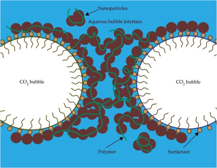
Polymers have been used to enhance foam stability because of their easy accessibility and low cost (Raghav Chaturvedi et al., 2018; Zhou et al., 2020). Often employed in conjunction with surfactants, polymers play a crucial role in stabilising foam, offering distinct advantages. Unlike surfactants, a small percentage of a polymer is sufficient to improve foam stability and viscosity (Ahmed et al., 2017). Similar to surfactants, some polymers with small molecular sizes adsorb at the lamella, which reduces gas permeability (Shah et al., 2016). Polymer chains can bind with surfactants at the lamella due to the induced electrostatic and hydrophobic forces among them, as depicted in Fig. 8reinforcing foam stability. Some long chains of polymers may form a bridge at the liquid film (Zhou, Ranjith and Wanniarachchi, 2020). Polymers are viscous fluids that increase the viscosity of the foaming solution, thus reducing the velocity of the drained liquid. As a result, the liquid drainage rate is reduced. They also prevent the desorption of surfactants from the lamella, limiting coalescence and liquid drainage. Further, polymers enhance the foaming solution's viscoelasticity, improving foam stability (Hernando et al., 2016). However, polymers may break down at high temperatures, leading to formation damage, reduced reservoir conductivity and large residue mass due to their large chains and concentration (Liang et al., 2016a; Liang, Al-Muntasheri and Li, 2016; Wang et al., 2017a). When considering the type of polymer used to generate foam, partially HPAM polymer is commonly used for oil recovery. Guar gum is a water-soluble polymer that improves foam stability with SiO2-NPs (Emrani and Nasr-El-Din, 2017). The following section delves into the rheological changes of polymer-stabilised CO₂ foam, providing critical insights into foam behaviour under high temperature and pressure conditions.
 Fig. 8
3.2.1. Influence of temperature and pressure on polymer-stabilised CO₂ foam rheology
The temperature of the reservoir is one of the vital parameters in the stability of polymer-stabilised foam. Most polymers exhibit limited tolerance to high temperatures, with degradation typically initiating beyond 90°C; most advanced polymers begin to degrade, resulting in decreased thickening ability (Emrani and Nasr-El-Din, 2017; Majeed et al., 2021). Therefore, the application of polymer-stabilised foam is restricted under elevated temperatures (Majeed et al., 2021). Nevertheless, a few previous studies have explored the stability of surfactant-polymer stabilised CO₂ foam at high temperatures and high-pressure conditions (Al-Darweesh et al., 2022; AlYousef et al., 2022; Thakore et al., 2024). For example, Al-Darweesh et al. (2022) investigated the performance of CO₂ foam with Armovis viscoelastic surfactant and superpusher SAV 522 anionic polymer at 6.89MPa, 120°C and 100 1/s shear rate, as shown in Fig. 9. The study revealed a notable reduction in the bubble count by 50% after 3.5min in surfactant only solution, illustrating the foam ageing process with time. Introducing 0.25wt% superpusher accelerated this reduction to 3min, whereas 0.5wt% superpusher achieved this in 7.3min. Armovis alone exhibited substantial coarsening, with the initial 60μm bubble radius increasing by 146% within 10 minutes. However, the addition of 0.25wt% superpusher slowed foam ageing, with an initial 83μm bubble growing by 81%, while adding 0.5wt% superpusher exhibited further slowdown of the foam ageing and an initial 63μm growing by 50% after 10min (Al-Darweesh et al., 2022). This difference was attributed to the polymer molecules adsorbing at the liquid/gas interface, reducing the gas permeability of the foam film and thereby mitigating coarsening mechanisms (Shah et al., 2016). Moreover, the half-life of Armovis only solution was 11.68min, which was significantly improved to 135min by adding 0.5wt% superpusher. The interaction between polymer and surfactant in the liquid film bolstered its strength, thereby reducing liquid drainage (Al-Darweesh et al., 2022).
 Fig. 9
The apparent viscosity of surfactant-polymer stabilised CO₂ foam represents another crucial aspect of foam stability. AlYousef et al. (2022) utilised alkyl amine surfactant at 10gpt (gallon per thousand gallons) and polymer at 8.9gpt under 100°C and 22.06MPa conditions. The apparent viscosity of alkyl amine surfactant stabilised CO₂ foam measured 20cP at 50 1/s shear rate, which was increased to 100cP with the addition of 8.9gpt polymer. Similarly, Al-Darweesh et at. (2022) observed that the apparent viscosity of Armovis surfactant-only solution was 35cP, which was increased to 50cP by adding superpusher SAV 522 anionic polymer under conditions of 6.89MPa, 120°C and 100 1/s shear rate. Therefore, it is evident that augmenting a surfactant solution with polymer improves the viscosity of CO₂ foam by binding surfactants at the liquid-gas interface.
The incorporation of polymers in surfactant-NP stabilised CO₂ foam is another vital aspect. Emrani and Nasr-El-Din (2017) found that although the half-life of surfactant-polymer (0.5wt%AOS + 20ppt guar)-stabilised CO₂ foam is improved with increasing temperature from 25°C to 80°C compared to surfactant-stabilised CO₂ foam (0.5wt% AOS). The introduction of SiO2 and Fe2O3 (Ferric oxide) NPs significantly enhances the stability of CO₂ foam beyond that achieved by surfactant-polymer stabilised CO₂ foam, as depicted in Fig. 10 (Emrani and Nasr-El-Din, 2017). The presence of polymer in NP-surfactant-stabilised CO₂ foam causes interwoven interactions among surfactant, polymer and NPs, solidifying the distribution of NPs and strengthening the lamella's structural integrity. As a result, the interfacial morphology of the solution improves and stabilises the CO₂ foam, further reducing the liquid drainage (Fu and Liu, 2020). However, NP-surfactant stabilised CO₂ foam has greater stability than NP-polymer surfactant-stabilised CO₂ foam between 25°C to 80°C due to the predominance of attractive forces over repletion forces in the NP-polymer-surfactant solution, leading to NP aggregation and separation of NP from the lamella (Emrani and Nasr-El-Din, 2017). Given the limited reports on the influence of temperature and pressure on polymer-stabilised CO₂ foam, further studies are required to draw robust conclusions in this research area.
 Fig. 10
3.3. NP-stabilised CO₂ foam
The foam structure undergoes continuous changes over time, rendering it inherently unstable due to processes such as foam coalescence, coarsening and liquid drainage (Yekeen et al., 2018). These changes arise from four main underlying factors (Binks, Kirkland and Rodrigues, 2008; Horozov, 2008; Kaptay, 2006). First, removal from surfactant (foaming agent) from the gas-liquid interface with low energy availability, which leads to foam instability. Second, an increase in the pressure difference (capillary pressure) at the gas-liquid interface, accelerating the rate of coalescence. Third, the progressive reduction in the distance between adjacent bubbles over time, leading to bubbles rupture. Lastly, the elevated liquid drainage rate attributed to the low viscosity of the liquid phase. As discussed in the following sections, the introduction of NPs into the surfactant foam structure offers a means to enhance foam stability.
NPs positioned at the foam lamellae play a crucial role in enhancing foam stability through four principal mechanisms. The mechanisms are increasing particle detachment energy, reducing the capillary pressure, arrangement of NPs during liquid drainage and increasing the maximum capillary pressure at coalescence (AlYousef, Almobarky and Schechter, 2017; AlYousef, Almobarky and Schechter, 2018; Singh and Mohanty, 2015a). Firstly, the detachment energy, denoting the energy required to desorb the NPs on the lamellae, underscores the quasi-irreversible adsorption of NPs onto the lamellae due to their high detachment energy (Shrestha et al., 2006). The detachment energy of NP-stabilised foam is higher than that of surfactant and polymer-stabilised foams. Detachment energy can be calculated by Eq. 6:(6)
Several parameters influence the stability of NP-stabilised foam, including NP concentration, NP size, hydrophilicity, hydrophobicity, salinity, temperature, pressure, NP shape, flow rate, and NP type (Ab Rasid et al., 2022; Majeed et al., 2021). The type of NP used to generate the CO₂ foam notably impacts foam stability, with several studies highlighting that foam stabilised by NPs has more potential advantages than surfactant-stabilised foam (Espinosa et al., 2010). Majeed et al. (2021) reported that NP-stabilised foam withstands high-temperature conditions. Espinosa et al. (2010) underscored the economic attractiveness of NPs compared to surfactants, along with their ability to minimise the adsorption of other chemical additives (such as surfactants) on reservoir rocks (Espinosa et al., 2010). For instance, a study demonstrated the use of silica NPs to generate stable CO₂ foam, resulting in a reduction of the mobility of CO₂ with silica NPs (Fu, Yu and Liu, 2018). Similarly, another study reported that surface-modified silica NPs can produce stable CO₂ foam (Worthen et al., 2013b). Further, Emrani and Nasr-El-Din (2017) used AOS surfactant with silica NPs and found that foam generated by surfactant-NPs is more stable than that generated by a surfactant-polymer system. Additionally, Bayat, Rajaei and Junin (2016) studied different types of NPs with CO₂ foam, including SiO2, Al2O3 (Aluminum Oxide), TiO2 (Titanium dioxide) and CuO (Copper(II) oxide), and concluded that SiO2 and Al2O3 NPs generated more stable CO₂ foam than TiO2 and CuO NPs (Bayat, Rajaei and Junin, 2016). Moreover, fly ash was found to stabilise CO₂ foam (Lee et al., 2015). The concentration of the NPs also plays a vital role in foam stabilisation, with optimum concentrations maximising foam stability. Table 3 summarises the optimum concentrations of different NPs with SDS and CTAB surfactant-stabilised CO₂ foam (Majeed et al., 2021). The effects of hydrophilicity and hydrophobicity have also gained attention concerning CO₂ foam stability, although previous studies have yielded contradictory and inconclusive findings in this regard. (Majeed et al., 2021). For example, some studies found that foams generated with hydrophilic particles were more stable than those generated with hydrophobic particles (Dippenaar, 1982a; Dippenaar, 1982b). Some others studies reported that hydrophobic particles made a barrier around CO₂ bubbles, contributing to the production of more stable CO₂ foams (Adkins et al., 2007; Stocco et al., 2011; Worthen et al., 2013a). Table 4 provides a summary of selected studies on the use of NPs to stabilise foam under high-pressure and high-temperature conditions.
| Surfactant | CMC | NPs | NPs concentration (wt%) |
|---|---|---|---|
| SDS | 7mM | BN (Boron nitride) | 0.25 |
| SDS | 7mM | ZrO2 (Zirconium dioxide) | 0.5 |
| SDS | 7mM | SiO2 | 0.5 |
| SDS | 7mM | Al2O3 | 0.1 |
| SDS | 7mM | CaCO3 (Calcium carbonate) | 0.25 |
| CTAB | 1.2mM | BN | 0.5 |
| CTAB | 1.2mM | ZrO2 | 0.5 |
| CTAB | 1.2mM | SiO2 | 0.25 |
| CTAB | 1.2mM | Al2O3 | 0.25 |
| CTAB | 1.2mM | CaCO3 | 0.25 |
| No | NP type | Surfactant | Additives and remarks | Temperature (°C) | Pressure (MPa) | Main findings related to temperature-dependent characteristics | Main findings related to pressure-dependent characteristics | Reference |
|---|---|---|---|---|---|---|---|---|
| 1 | SiO2, Fe2O3 | AOS | Ambient - 150°C | 0.5-3MPa | At high temperatures (150°C), surface tension increased with the addition of SiO2 NPs. It could occur due to gas diffusion and hydrogen bonds broken between water molecules at the lamella. As the temperature rises, the structure at the interface degrades. | The surface tension of AOS-stabilised CO₂ foam decreased with pressure from 0.5MPa to 3MPa. | (Emrani and Nasr-El-Din, 2015) | |
| 2 | CaCO3 | CTAB |
N₂: CO₂ = 1:2 (gas phase) |
25°C-80°C | Temperature affected foam stability and foamability. Incorporating 5wt% CaCO3NPs improved thermal stability. Despite a 68% reduction in half-life at 50°C and an 83% reduction at 80°C, the CaCO3 NP-stabilized foam still outlasted CTAB alone by approximately 22 times at 80°C. | (Mehairi, Khoshnazar and Husein, 2024) | ||
| 3 | Modified SiO2 | 25°C-80°C | 20.7MPa | Micrographs of medium coverage SiO2NPs show bubble size increasing from 46μm at 25°C to 63μm at 70°C and 71μm at 80°C with 90% CO₂ foam quality. This growth stems from higher capillary pressure and accelerated CO₂ diffusion. Smaller bubbles disappearing within seconds also contribute to coarsening. | (Alzobaidi et al., 2017b) | |||
| 4 | SiO2(65nm) | Hexadecyl hydroxypropyl sulfobetaine | 70°C | 8MPa | At elevated temperatures, the gas transfer rate through the film hastened, leading to film thinning and bubbles rupture. | (Li et al., 2019) | ||
| 5 | SiO2(7nm) | 20°C - 72°C |
8.96 MPa |
As the temperature rose, the apparent viscosity of CO₂ foam decreased. It decreased dramatically from 24.8cp to 5.5cp as the temperature rose from room temperature to 43°C and gradually decreased to 3cp as the temperature rose to 72 degrees Celsius. Decreasing the solution's viscosity and increasing the molecular kinetic energy contributed to low, stable CO₂ foam. | (Fu and Liu, 2021a) | |||
| 6 |
TiO2(18nm) SiO2 (5-20nm) CuO (40nm) Al2O3(20nm) CNT (<8nm) |
Triton X-100, SDS, TX-100, CTAB | 80°C | 10.34MPa | Perfectly spherical SiO2NPs stabilised foam reliably at high temperatures, with or without oil. Their shape and orientation at interfaces are vital for stabilising foam and screening NPs. | Higher NP concentration improved sub-critical CO₂ foam stability. Optimal 0.5wt% SiO2concentration ensured maximum stability for supercritical CO₂ foam, indicating a minimum requirement of NPs at high pressure. | (Yekeen et al., 2021) | |
| 7 | SiO2(36nm-146nm) | SDS | 30°C-100°C | Ambient-1.2MPa | The stability of the foam was discovered to rely significantly on the temperature of the test, with Pickering foam showing increased foam degradation above 90°C. | (Chaturvedi et al., 2021) | ||
| 8 | SiO2(140nm) | AOS | Guar-gum | 25°C-121°C | 2.07MPa | At elevated temperatures, there was a notable increase in the difference in pressure drop across the core. This phenomenon can be attributed to the decrease in brine viscosity, which decreased from 0.9cP to 0.106cP at 25°C and 121°C, respectively. | (Emrani, Ibrahim and Nasr-El-Din, 2017) | |
| 9 | CNC | AOS | Ambient - 150°C | 2.7MPa | The foam tends to collapse at a notably accelerated rate, with foam lifespan decreasing to 60 minutes at 100°C and 30 minutes at 150°C, respectively, with 1% CNC. These effects were particularly pronounced in foam, which consisted solely of surfactants. | (Etemad, Kantzas and Bryant, 2020) | ||
| 10 | SiO2and GO | SDS, NP-40, CTAC, AOS | Guar, crosslinker, and clay | 23°C-200°C | 0.69MPa-6.9MPa | Observations revealed a decrease in foam half-life with increasing temperature. Among the surfactants examined, AOS foams demonstrated superior thermal stability at higher temperatures. The half-life of SiO2-AOS stabilized CO₂ foam was 160 minutes at 100°C under 6.9 MPa pressure, but this decreased to approximately 17 minutes at 200°C under 6.9 MPa pressure. | The half-life of SiO2-AOS stabilized CO₂ foam improved with increasing pressure, even at high temperatures. Initially, the half-life was around 2 minutes at 0.69 MPa at 200°C, then rose to nearly 17 minutes at 6.9 MPa at 200°C. | (Thakore et al., 2024) |
| 11 | SiO2(7nm) | SDS | HEC | 43°C-72°C | The apparent viscosity declined from approximately 20cp at 43°C to 13cp at 72°C. | (Fu and Liu, 2020) | ||
| 12 | SiO2 | AOS | Guar | 25°C-80°C | 2.06MPa-5.52MPa | The CO₂ foam stabilised with 0.5 wt% AOS and 0.1 wt% SiO2demonstrates a higher half-life between 25°C and 80°C. However, as the temperature increases within this range, the half-life decreases. Specifically, it decreases from around 5 hours to nearly 0.8 hours under 2.06 MPa. | The half-life of the CO₂ foam stabilized with 0.5 wt% AOS and 0.1 wt% SiO2nanoparticles declined from nearly 4.5 hours to 0.77 hours as the pressure increased from 2.06 MPa to 5.52 MPa. | (Emrani and Nasr-El-Din, 2017) |
| 13 | SiO2(12nm) | CD 1045TM(Commercial Surfactant) | 25°C-60°C | 8.27MPa-13.79MPa | The height of the CO₂ foam reduced as the temperature rose. At 60°C, no CO₂ foam was observed in the sapphire tube at 10.34MPa. | With increased pressure, a more significant amount of CO₂ foam was produced in the sapphire tube. The heights of the CO₂ foam in the observation cell were 0.65cm, 1.79cm, and 2.49cm for pressures of 8.27MPa, 10.34MPa, and 13.79MPa, respectively. | (Yu et al., 2012) | |
| 14 | SiO2(7nm) | AOS | 20°C-60°C | 5.5MPa-9.5MPa | The lowest foamability, characterised by the lowest foam height of 6.6 mm, and the most minor foam stability, with the highest foam decay rate of 0.95, were observed at 30°C, near the CO₂ supercritical temperature of 31.1°C. The foam height decreased from approximately 20 mm to 12 mm as the temperature rose from 40°C to 60°C. | Foamability gradually increased within the pressure range of 5.5 MPa to 8.5 MPa. However, it sharply rose beyond 8.5 MPa, reaching the peak foam height of 33.8 mm. | (Song et al., 2022) | |
| 15 | SiO2(20nm) | SDS | 20°C-80°C | 2MPa-12MPa | The half-life and foam volume of SiO2-SDS-stabilised CO₂ foam was higher than that of SDS-only stabilised foam. However, the half-life of SiO2-SDS-stabilized CO₂ foam decreased with increasing temperature, declining from nearly 65 minutes to 25 minutes in the temperature range of 20°C to 80°C. | As the pressure increases, the foam volume and half-life at the two examined temperatures also increase. Specifically, the half-life increased from around 1 hour to 10.5 hours when the pressure was increased from 2 MPa to 12 MPa at 40°C. | (Li, Li and Wang, 2016) |
NP adsorption into the gas-liquid interface is a key factor in enhancing CO₂ foam stability (Li et al., 2017b). Li et al. (2017b) illustrated the synergistic effects between surfactants and NPs in CO₂ foam, employing CTAB surfactant with SiO2NPs, as shown in Fig. 11. The conceptual illustration reveals the intricate relationship between the surfactant concentration and NP adsorption percentage. In the initial phase (region A), the concentration of CTAB surfactant is very low (the proportion of CTAB/SiO2 is almost the same). Therefore, the NPs are predominately distributed in the bulk liquid phase, exhibiting the surfaces of the NPs are hydrophilic, and limited synergistic effects. As the CTAB concentration increases (region B), the adsorption of CTAB onto NP surfaces initiates, with the hydrophilic end of the CTAB electrostatically attracted to the NPs’ surface while the hydrophobic end remains exposed to the bulk solution. This results in an increase in the NP's hydrophobicity by forming a single hydrophobic CTAB layer, facilitating their migration to the liquid-gas interface. It shows a synergistic effect between CTAB and SiO2 NPs and increases the stability of the foam. With the further increase of the CTAB concentration to the optimal range (region C), a moderate amount of CTAB surfactants is adsorbed onto the SiO2 NPs, and CTAB forms either tight single or incomplete double hydrophobic layers on SiO2 NPs. This process increases the hydrophobicity of SiO2 NP and further enhances the adsorption of SiO2 NPs onto the gas-liquid interface, significantly improving foam stability by a strong synergistic effect. Beyond the optimal concentration of CTAB, the interfacial tension cannot be minimised. This concentration is called the critical micelle concentration (CMC) of surfactant. After the CMC, the surfactant molecules begin to assemble by themselves (region D). Due to the further adsorption of CTAB, the SiO2 NPs form a double hydrophilic layer by facing hydrophilic ends outwards (outer layer of the NP). Therefore, the hydrophilicity of the NPs is increased, and they then move to the bulk solution from the gas-liquid interface. As a result, the synergistic effect is markedly weakened, and the foam's stability is significantly reduced (Doroudian Rad et al., 2018; Li et al., 2017b). Overall, the addition of surfactant at CMC is vital to the achievement of optimum foam stability.
 Fig. 11
3.3.1. Influence of temperature on NP- stabilised CO₂ foam rheology
The thermal stability of foam is a vital requirement for its application at high temperatures (Kim et al., 2016), with modern advancements in nanoscience technologies offering potential avenues for stabilising CO₂ foam under high temperatures (Fu and Liu, 2020; Raghav Chaturvedi et al., 2018). A pioneering study focusing on the generation of stable CO₂ foam with surface-modified SiO2NPs, building upon earlier research that delved into the efficacy of nanoparticles in foam stabilisation (Dickson, Binks and Johnston, 2004). Although NP-stabilised foams have the potential to withstand high-temperature reservoir conditions, their stability tends to decrease with increasing temperature, as summarised in Table 4. The adsorption of NPs at the lamellae creates a steric barrier, which resists bubble coalescence (Singh and Mohanty, 2015b). Chaturvedi et al. (2021) investigated the stability of Pickering (foam including emulsion) CO₂ foam via microscopic analysis, employing silica nanofluid (36nm, 0.1wt%) to prepare the foam. Observations revealed that at 25°C, the average bubble size temperature was 20μm, which increased to nearly 180 μm at 50°C, escalating further bubble expansion to 260 μm at 90°C. Therefore, it is evident that the size of bubbles increases with increasing temperature. Similarly, Emrani, Ibrahim and Nasr-El-Din (2017) observed a bubble size increase between 25°C to 60°C in AOS + guar gum stabilised CO₂ foam. As the kinetic energy of NPs increases at high temperatures, the rates of agglomeration and collision of NPs are raised (Metin et al., 2014). As a result, the involvement of NPs in bubble stabilisation diminishes. Chaturvedi et al. (2021) further increased the temperature to 100°C and observed that bubbles deformed rapidly (in less than 5min) and subsequent liquid evaporation.
As discussed earlier, the stability of foam has been extensively analysed through measurements of foam height and half-life (Song et al., 2022). Etemad, Kantzas and Bryant (2020) explored the changes in normalised AOS-40 stabilised CO₂ foam height over time with different CNC (Cellulose nanocrystal) NPs, as illustrated in Fig. 12. It is apparent that the normalised CO₂ foam height reduced with time at room temperature (RT), 100°C, and 150°C with 0% CNC NPs (without CNC NPs). However, the addition of CNC NPs to AOS-40 stabilised CO₂ foam resulted in a substantial improvement in the normalised foam height. For example, the half-life of the sole surfactant solution was 50min at RT, which was improved to 260min with 0.5% CNC NPs, and notably did not reach half-life until 550min with 1% CNC NPs. Nonetheless, a noticeable reduction in the half-life of CO₂ foam was observed with increasing temperatures. The half-life of the surfactant-only solution was less than 7min at 100°C and 3min at 150°C. By adding CNC NPs, the half-life time of the solution was improved even at high temperatures, more than 10min at 100°C and 5min at 150°C with 1% CNC NPs (Etemad, Kantzas and Bryant, 2020).
 Fig. 12
Similarly, Thakore et al. (2024) investigated the half-life of CO₂ foam with AOS, SDS, NP40 and CTAC surfactants with SiO2 and GO (graphene oxide) NPs. They concluded that the half-life of CO₂ foam reduced from 90°C to 200°C in all the foam solutions, while CTAC + GO showed a greater maximum half-life of 30 sec at 90°C than other SiO2 and GO NP- stabilised foams. The addition of NPs improves foam stability to some extent, a phenomenon attributed to detachment energy and attractive force between NPs, which can be determined by contact angle and zeta potential energy (Emrani and Nasr-El-Din, 2017). However, an optimum concentration of NP is pivotal for enhancing foam stability; beyond that, the stability of foam decreases (Emrani and Nasr-El-Din, 2017).
The half-life reduction with increasing temperatures can be attributed to three primary factors. First, both surfactants and NPs exhibit greater kinetic energy at high temperatures, reducing their adsorption at the lamellae. Therefore, interfacial viscoelastic modulus decreases, and interfacial tension increases with increasing temperature. Consequently, CO₂ foam instability occurs (Li, Li and Wang, 2016). Second, increasing temperature reduces the viscosity of the solution, which accelerates the liquid drainage and lowers the stability of CO₂ foam (Li, Li and Wang, 2016). Last, water evaporation at the lamellas surges with rising temperature, which accelerates the coalescence and decreases the stability of CO₂ foam (Li, Li and Wang, 2016). Therefore, it becomes evident that increasing temperature leads to a reduction in the half-life and volume of CO₂ foam.
Furthermore, the stability of NP-stabilised CO₂ foam is influenced by various parameters. Among these, the viscosity of the foam is one of the critical parameters for hydrofracking Enhanced Geothermal Systems (EGSs) (Thakore et al., 2020), with the apparent viscosity of NP-stabilised CO₂ foam declining as temperature increases (Fu and Liu, 2021a; Fu and Liu, 2021b). Fu and Liu (2020)studied the apparent viscosity of NP- stabilised CO₂ foam in the temperature range of 43°C to 72°C. The study observed that 0.02% SDS surfactant + 0.02% HEC (Hydroxyethyl cellulose) polymer + SiO2 NPs stabilised CO₂ foam exhibited higher apparent viscosity than CO₂ foam stabilised by solely SDS surfactant + SiO2 NPs (Fu and Liu, 2020). In particular, the apparent viscosity declined from approximately 20cp at 43°C to 13cp at 72°C for the solution with 0.02% SDS+ 0.02% HEC + SiO2 NPs.
The contact angle represents another vital parameter determining the interaction between bubbles and NPs. It is well-stabilised that solid hydrophobic particles reduce foaming ability (Emrani and Nasr-El-Din, 2017). The contact angle is directly proportional to the energy required to move a particle from the interface to the bulk solution (E), as depicted in the following equation, where θis the contact angle at the aqueous solution, γ is the surface tension, and r is the particle's radius.(7)
According to Eq.7, the detachment energy is very low for contact angles between 0 and 30° or 150°-180° where stable foam cannot be generated (stable foam can be generated at a contact angle close to 90°) (Binks, 2002). A studied the contact angle of AOS/guar/SiO2 stabilised CO₂ foam using the sessile drop method. They found that the contact angle reduces from 86° (at 25°C) to 30° (at 80°C) with increasing temperature, indicating that foam stability is reduced (Emrani and Nasr-El-Din, 2017).
In summary, the stability of NP/CO₂ foam decreases with increasing temperature, exhibiting similar behaviour to the surfactant-stabilised foam. However, the stability of NP-stabilised CO₂ is greater than that of surfactant-stabilised CO₂ foam under high-temperature conditions (Ab Rasid et al., 2022). Despite the availability of limited studies above 100°C, further research is warranted to gain a deeper understanding of CO₂ foam stability in high-temperature applications.
3.3.2. Influence of pressure on NP-stabilised CO₂ foam
A few studies have investigated the influence of pressure on NP-stabilised CO₂ foam (Emrani and Nasr-El-Din, 2017; Li, Li and Wang, 2016; Song et al., 2022; Yu et al., 2012), yet comprehensive investigations are still vital in this research area. Emrani and Nasr-El-Din (2017) investigated the effect of pressure on the half-life of NP- stabilised CO₂ foam across the range from 2MPa to 5.5MPa at 25°C. Their findings revealed that the half-life of CO₂ foam stabilised with surfactant, polymer, and NPs decreases with increasing pressure (Emrani and Nasr-El-Din, 2017). Illustrated in Fig. 13, the half-life of 0.5wt% AOS + 0.1wt% SiO2 NP-stabilised CO₂ foam declined from nearly 4.5 hrs to 0.77 hrs, while that of 0.5wt% AOS-stabilised CO₂ foam reduced from about 0.5hr to 0.1hr between 2MPa to 5.5MPa. Fe2O3 exhibiting a shorter half-life than SiO2 NP-stabilised CO₂ foam. Similarly, Yu et al. (2012) observed a reduction in the half-life time of NP-stabilised CO₂ foam with increasing pressure from 8.3MPa to 13.8MPa. Increasing pressure enhanced the solubility of CO₂ in water, which caused gas diffusion and accelerated liquid drainage, consequently reducing foam stability.
 Fig. 13
However, contrasting observations were made by Song et al. (2022) who noted that increasing pressure from 5.5MPa to 9.5MPa resulted in an increased foam height and a decreased foam decay rate. Similarly, Li, Li and Wang (2016) reported that raising pressure from 2MPa to 12MPa contributes to increasing foam half-life, as depicted in Fig. 14. The interfacial tension was reduced with increasing pressure, alongside an increase in the viscoelastic modulus for SDS/SiO2 NP-stabilised CO₂ foam. Moreover, CO₂ foam density and volume showed a gradual increase with rising pressure, particularly stabilising the foam beyond 8MPa. Furthermore, Li, Li and Wang (2016) discovered that the half-life of SDS/SiO2 CO₂ foam at 10MPa pressure is higher than at normal pressure, indicating that increased pressure is advantageous to CO₂ foam stability. However, the existing literature on the effect of pressure on NP-stabilised CO₂ foam remains insufficient to draw conclusions under high pressure.
 Fig. 14
4. Some field applications of CO₂ foam as a stimulation fluid
Foam-based stimulation fluid has gained considerable attention since its first application in Devonian shale, Youngstown, Ohio, the USA, in 1975 (Frohne, 1976; Wanniarachchi et al., 2015). Subsequently, high-quality CO₂ foam-based stimulation fluids were introduced in 1982. (Al-Dhamen and Soriano, 2015; Almond and Harris, 1986). While CO₂ gas utilisation for energy recovery ranged from 5% to 50% in the 1950s, the lower limit of this range was mostly the practice. However, the adoption of 65% -80% CO₂ gas has notably increased viscosity, thus enhancing the proppant-carrying capacity in the formation (Reidenbach et al., 1986). Moreover, CO₂ foam minimises interfacial tension, thereby contributing to greater foam stability and demonstrating compatibility with formation fluids while reducing the pumping pressure compared with N₂ foam (Wamock, Harris and King, 1985). Notably, CO₂ foams cause less damage to the injection region than gelled and slickwater fluids (Reynolds, Bachman and Peters, 2014a). The post-fracture productivity index (PI) (PI of post-fracture well/ PI of zero skin well) of CO₂ foam is also considerably better than that of slickwater (Reynolds, Bachman and Peters, 2014a), making CO₂ one of the best fluids for stimulation. The following sections provide a brief overview of selected field applications of CO₂ foam stimulation.
4.1. Heritage Montney Field, British Columbia, Canada.
Reynolds, Bachman and Peters (2014a) examined the field application of foam-based stimulation fluid at Heritage Montney Field, British Columbia, Canada. They compared the efficiency of different types of stimulation fluid, including slick water, gelled water and foam-based fluid (CO₂, N₂ and binary foam). Twelve multiple fractured horizontal wells were created by CO₂ foam, and ten wells were created by N₂ foam. Both CO₂ and N₂ foam possessed the minimum damage to the injection well compared to silk water and gelled water. The lowest amount of proppant per stage was pumped in CO₂ foam fractured wells, achieving the most efficient fracture conductivity per unit of proppants. The research concluded that foam-based stimulation is superior to slickwater, with CO₂ foam emerging as the most efficient stimulation method for foam-based stimulation fluids (Reynolds, Bachman and Peters, 2014a).
4.2. Eastern Province, Saudi Arabia
Since the beginning of gas production in Saudi Arabia, various hydraulic stimulation techniques have been employed across many fields. Among these, CO₂ in either foam or energised state stimulation fluid form has been used in the application of acid stimulation (Malik et al., 2015; Sanchez et al., 2015). Al-Dhamen and Soriano (2015) noted that using CO₂ foam led to high hydrocarbon productivity, reduced or eliminated the requirement of the liquid phase, minimised the liquid entrapment in the formation, and increased gas gain percentage by 50% in well WD-1. Additionally, the use of CO₂ foam facilitated fast and efficient cleaning (<1 day) compared to crosslinked gel in low-permeable sandstone formations (Al-Dhamen and Soriano, 2015).
4.3. Arkansas-Louisiana-Texas Region
CO₂ foam-based stimulation has proven effective in the Arkansas-Louisiana-Texas region for enhancing oil and gas recoveries from low-permeability sandstone and carbonate formations at depths ranging from 884m to 4267m. Operating under reservoir temperatures between 48°C and 188°C and pressures from 7MPa to 91MPa, CO₂ foam has demonstrated its utility, particularly in deep and high-temperature water conditions due to the high density of water/CO₂. Numerous fields in Arkansas-Louisiana-Texas, including Arkana, Arkana Trend, Dorcheat Macedonia, Greenwood Waskom, Mira, N.E.Bethany, Shongaloo, Vernon and Winnsboro, have benefitted from CO₂ foam stimulation. For instance, the Dorcheat Macedonia Field is a testament to the successful application of CO₂ foam stimulation. In this case, the injection of 151.4m3 of CO₂ foam, flowing at 3.97m3/min and carrying 36,287kg proppants at a concentration of 4912.9kg/m3, resulted in a fracture half-length of 152.4m. Prominent wells such as Willis D-1 and Paxton B-1 wells have yielded substantial recoveries, with the former producing 12,720m3 of oil and 8.8
4.4. Western Canadian sedimentary basin
Since 1998, the application of surfactant-gel fluids has been to be successful in the sedimentary basin of Western Canada. These fluids, when foamed with either N₂ or CO₂ gas, have proven effective, with N₂ foam being economically advantageous for shallower wells and CO₂ foam for deeper wells. Over 260 CO₂ foam and 2900 N₂ foam treatments carried out until 2008 have demonstrated the efficacy of the technique in proppant placement in formations in the sedimentary basin. Notably, Poly CO₂ (40% methanol/water gel) treatment has achieved a 95% placement success rate in insensitive water formations, offering economic viability with foam qualities ranging from 10% to 53%. The success rate was greater than either crosslinked gel or energised linear get (Gupta and Hlidek, 2010). Gupta and Hlidek (2010) concluded the cost-saving benefits of foam-based stimulation fluids, particularly in reducing freshwater usage and water flow-back expenses.
While some pilot-scale studies have demonstrated successful implementation with CO₂ foam stimulation, its application in deep rock formations is still challenging due to field-scale issues. Foam propagation in deep wellbores poses significant challenges primarily stemming from the instability of CO₂ foam, which directly impacts the propagation rate and efficiency at the subsurface. Understanding the temperature and pressure-dependent properties of lamellae is critical for addressing these challenges. Another major concern is the adsorption of surfactants into reservoir rock, which hinders the effectiveness of the foam stimulation. To mitigate this issue, it is recommended that surfactants with a similar charge to that of the reservoir be selected to minimise surfactant adsorption into the formation (Majeed et al., 2021). Further research is required on the selection of suitable CO₂ foam that exhibits thermal and high-pressure stability, economic viability, and minimal absorption into reservoir formations.
5. Conclusions and Recommendations
Global energy demand is on a continuous rise, driven by economic and population growth. Among the various energy resources available, geothermal energy has vast potential to contribute to meet this escalating energy demand. Concurrently, the increasing atmospheric CO₂ concentration leads to climate changes and environmental impacts. In light of these challenges, recovering geothermal energy through CO₂ foam stimulation could promise a dual solution addressing both energy needs and contributing to CO₂ sequestration. The following conclusions are drawn from a critical review of the use of CO₂ foam for reservoir stimulation applications.
-
•
Three interdependent phenomena influence foam decay over time: liquid drainage, coarsening, and coalescence. To stabilise CO₂ foam, surfactants, polymers, and NPs have been employed. Additionally, incorporating a small amount of N₂ into the CO₂ foaming solution has been shown to enhance its stability post-critical point.
-
•
Various parameters influence the stability of CO₂ foam, with temperature and pressure exerting the most significant effects.
-
•
Considering the time-dependent behaviour of surfactant-stabilised CO₂ foam, foam texture expansion and reduced half-life contribute to foam decay. Notably, UC22AMPM-stabilised CO₂ foam had a 300-minute half-life at 100°C and 10MPa, depicting promising application at reservoir conditions.
-
•
At elevated temperatures, the apparent viscosity and half-life of surfactant-stabilised CO₂ foam are reduced. However, certain surfactants, such as OAPB and AOS with TEGO, demonstrate considerable stability up to 120°C.
-
•
Regarding polymer-stabilised CO₂ foam, the addition of even a small quantity of polymers has been shown to significantly enhance CO₂ foam stability. HPAM and Guar gum are the most widely used polymers for enhanced oil recovery. However, the polymer chains may undergo breakage at elevated temperatures, potentially causing formation damage.
-
•
CO₂ foam stabilised by NPs represents a promising approach to enhancing foam stability. In comparison to surfactant and polymer-stabilised foams, NP-stabilised CO₂ foam exhibits superior stability. Commonly used NPs for foam stabilisation include SiO2, Fe2O3 and Al2O3.
-
•
Increasing time and temperature negatively influence NP-stabilised CO₂ foam, which reduces foam half-life and apparent viscosity, increasing foam decay and surface tension. Studies have reported contradictory observations for surfactant-polymer-NP stabilised foam half-life and decay rate with pressure; therefore, further comprehensive studies are needed to derive strong conclusions.
-
•
CO₂ and N₂-based foam have been applied to natural gas recovery, with some pilot studies showcasing the successful implementation of CO₂ foam stimulation. The stability of CO₂ foam decreases with increasing temperature, which is the most critical consideration for geothermal applications.
Advances in nanoscience technologies have yielded promising innovations for stabilising CO₂ foam, even under higher temperatures (up to 150°C), by incorporating appropriate proportions of additives. Nevertheless, comprehensive research studies are required to understand the foam decay mechanism and facilitate the development of stable foam under challenging conditions applicable to geothermal energy recovery.
Declaration of Competing Interest
The authors affirm that no financial interests or personal conflicts would influence the work reported in this study.
Role of the funding source
This work was supported by the Department of Civil Engineering, Monash University, Australia.
RDGF Harshini: Writing – original draft, Methodology, Formal analysis, Data curation. W.G.P. Kumari: Writing – review & editing. Ranjith PG, FTSE: Writing – review & editing, Supervision, Funding acquisition, Conceptualization. D.C. Zhang: Writing – review & editing
Uncited reference
AlYousef et al., 2017; AlYousef et al., 2018; Anandan et al., 2017; Avanthi Isaka et al., 2019; Biagi et al., 2015; Binks et al., 2008; Dickson et al., 2004; Farajzadeh et al., 2008; Faroughi et al., 2018; Foroutan et al., 2021; Fu et al., 2018; Goel et al., 2002; Heller et al., 1985; Li et al., 2016; Li et al., 2022; Liang et al., 2016; Liew et al., 2020; Mehairi et al., 2024; Reynolds et al., 2014b; Solbakken et al., 2013; Tong et al., 2018; Wamock et al., 1985; Xiao et al., 2022; Yekeen et al., 2018; Zhou et al., 2023; Zhou et al., 2020.
Declaration of Competing Interest
☒ The authors declare that they have no known competing financial interests or personal relationships that could have appeared to influence the work reported in this paper.
Data availability
Data will be made available on request.
© 2024 The Authors. Published by Elsevier B.V.