Highlights
-
•
The comparison between DCM - DC2 and DC2 - DC3, shows variations in the longitudinal and transverse reinforcement.
-
•
Buildings designed for DCM and DC3 ductility classes behave similarly.
-
•
There is a consistent linear trend where capacity design in shear exceeds seismic design demand for all ductility classes.
-
•
Capacity design in shear is generally higher than seismic design demand, indicating adequate shear resistance.
-
•
Some columns show substantially higher values, possibly due to higher moment values at lower storeys.
Abstract
Eurocode 8 is undergoing a thorough revision process encompassing a significant number of changes. In this work, the novel ductility classes, drift limits for damage limitation, local ductility conditions, and corresponding detailing prescriptions are presented and discussed. It is paramount to analyse and contrast these modifications with the current provisions of Eurocode 8. In order to assess the impact of such revisions, an extensive examination was conducted on ten symmetrical moment-resisting frame (MRF) buildings. These buildings are regular in plan and in elevation and are not torsionally flexible. The analysis was carried out following both the current and the second-generation Eurocode 8 provisions, with the results being compared in order to evaluate the effectiveness of the new design and detailing provisions. The study outcomes revealed that the DCM, DC2, and DC3 structures demonstrated different trends in their detailing demands for local ductility and capacity design. Differences in reinforcement quantities were observed between DCM and DC2, as well as DC2 and DC3, for 5-storey and 10-storey buildings. The design approach focused on individual member detailing requirements, to optimize design, while maintaining the overall concrete quantities. These insights offer valuable economic considerations for various structural configurations under strong seismic actions.
Keywords
Eurocode 8
Reinforcement detailing
Ductility
Seismic design
RC structures
1. Introduction
In recent decades, structural engineering has seen significant advancements in research and development of design practices, including theoretical, experimental, and numerical investigations by researchers working with practitioners’ feedback. This has led to the development of new construction materials and structural solutions and to the evolution of engineering professionals’ design methodologies.
Additionally, the study of the damage caused by recent seismic events to existing structures is critical in acquiring knowledge about their behaviour and identifying potential vulnerabilities, which, in turn, helps developing strategies and methodologies for strengthening existing structures and designing new ones.
This continuous development has led to the revision of the design codes, particularly Eurocode 8, and the need to validate the values and limits of different parameters, performance requirements and verification rules in the sections dedicated to reinforced concrete (RC) building design. Developing seismic design criteria based on performance requires a substantiated description of the probable response and behaviour of structures under seismic excitations they may be subjected to during their lifespan, which necessitates further advancements in estimating their expected behaviour.
Modern design procedures aim to produce a structural system with the required stiffness, strength, and deformation capacity to resist seismic events with acceptable performance. It thus requires an appropriately configured, sized, and detailed structural system to meet a building performance objective under earthquake loading.
Booth[1] refers that the upcoming generation of Eurocodes aims to align national practices more closely, seeking to minimise variations in values and procedures that allow for national discretion, as outlined in each country's National Application Document. While this approach may adequately address the requirements for most Eurocodes, recent advancements in earthquake engineering call for a more comprehensive and tailored approach within Eurocode 8.
The structural design process involves two stages. The first stage comprises the analysis for design actions, which includes defining the interstorey drift limitation, determining structural member cross-sections’ dimensions, and calculating reinforcement quantities for both static and seismic actions for verification of limit states. The analysis also considers second-order effects, global mechanism control checks (such as the capacity design procedure in flexure for members and beam-column joints), and capacity design in shear. The second stage involves detailing for local ductility, including verifying the minimum and maximum longitudinal reinforcement ratio, hoop spacing, and anchoring provisions.
The current Eurocode 8, EN 1998–1:2004[2], and the second generation of Eurocode 8, prEN 1998–1-2:2023[3] and FprEN 1998–1-1:2024[4], together with EN 1992–1-1:2004[5], specify how structural analysis and design is to be done for new RC buildings, including the required stiffness, strength and ductility models. These design codes specify how to calculate member design strengths and detailing requirements to achieve a building's safe and economic performance under an earthquake event. These specifications are defined in the Eurocodes under the form of design provisions.
To evaluate the effectiveness of the new design and detailing provisions in the second-generation Eurocode 8 compared to the existing version, a comparative design and analysis of ten symmetrical moment-resisting frame (MRF) buildings is conducted herein. These buildings are regular in plan and in elevation, not torsionally flexible, and have varying height configurations and seismic demands for ductility classes DCM, DC2, and DC3.
According to EN 1998–1:2004[2], the Ductility Class Medium (DCM) refers to a specific classification within the seismic design of structures where moderate ductility demands are expected for a given seismicity level. It represents an intermediate level of design requirements and is typically applied to structures located in regions with a moderate seismic hazard.
According to Plumier[6], within the framework of concrete building design as outlined in FprEN 1998–1-1:2024[4], DC2 is a classification that takes into consideration specific requirements: local overstrength capacity, local deformation capacity, and local energy dissipation capacity. Additionally, DC3 focuses also on the structure's ability to establish a global plastic mechanism at the Significant Damage (SD) limit state.
Additionally, Plumier[6] refers that DC2 falls between the previous categories of DCL and DCM, aiming to achieve a more cost-effective design approach.
In the context of this study, the design calculations for DCM structures were performed following the guidelines outlined in EN 1998–1:2004[2]. On the other hand, the design calculations for DC2 and DC3 structures were conducted following the provisions specified in prEN 1998–1-2:2023[3] and FprEN 1998–1-1:2024[4], respectively.
In the present work, the design method adopted is the force-based approach. The force-based approach includes the response spectrum method, i.e. a linear analysis incorporating the effects of overstrength and non-linear response through the behaviour factor (q). According to Elnashai[7], the behaviour factor may be defined as the minimum reduction coefficient corresponding to a specific level of ductility obtained from inelastic constant ductility spectra and elastic spectra at a given period (T).
2. Object of research and analysis
To conduct this study, a set of reinforced concrete moment-resistant frame (MRF) structures with different configurations was selected as the subject of analysis. These configurations were defined based on non-variable characteristics and parameters common to all buildings and specific variables for each building, as outlined in Table 1.
| Variable | Non-variable |
|---|---|
|
Buildings height Seismicity Ductility classes Inertial masses |
Structural system (frames) Interstorey height Span length Materials Vertical loads |
Ten structures models were built up, assumed symmetrical, and regular in plan and elevation as prescribed in EN 1998–1:2004[2], prEN 1998–1-2:2023[3]. These structures, listed in Table 2, were assigned to three different ductility classes (DCM, DC2, and DC3) based on the number of storeys and the maximum response spectral acceleration at the constant acceleration range (Sα). In the present study, Sα is defined as being 2,5∙ag∙S∙η, as per EN 1998–1:2004[2].
| Number of storeys | Sαm/s2 | Ductility class | Structure label |
|---|---|---|---|
| 5 | 5,0 | DCM | DCM.50.5 |
| DC2 | DC2.50.5 | ||
| DC3 | DC3.50.5 | ||
| 7,5 | DCM | DCM.75.5 | |
| DC3 | DC3.75.5 | ||
| 10 | 5,0 | DCM | DCM.50.10 |
| DC2 | DC2.50.10 | ||
| DC3 | DC3.50.10 | ||
| 7,5 | DCM | DCM.75.10 | |
| DC3 | DC3.75.10 |
2.1. Buildings geometry and structural system
The structures in this study consist of two building configurations: a five-storey building, shown in Fig. 1(a) and a ten-storey building, shown in Fig. 1(b).
 Fig. 1
The structural system for the buildings consists of a series of frames with an equal spacing of 6,0 m, typical of office buildings, as illustrated in Fig. 1(c). The floor-to-floor height is 3,0 m for all storeys, except for the ground storey, which is 4,0 m. The solid slab thickness is 15 cm at each storey.
2.2. Materials
The following materials are considered for all primary seismic members (beams and columns) of the structures under analysis:
-
•
Concrete C30/37
-
•
Reinforcement steel B500
The concrete properties are defined per EN 1992–1-1:2004[5] and EN 206–1:2007[8] standards, and its mechanical properties are shown in Table 3.
| Mechanical properties of concrete C30/37 | ||
|---|---|---|
| Characteristic compressive cylinder strength of concrete | fck (MPa) | 30 |
| Mean value of concrete cylinder compressive strength | fcm (MPa) | 38 |
| The design value of concrete compressive strength | fcd (MPa) | 20 |
| Characteristic axial tensile strength of concrete | fctk,0,95 (MPa) | 2,0 |
| Mean value of axial tensile strength of concrete | fctm (MPa) | 2,9 |
| Design value of tensile strength | fctd (MPa) | 1,3 |
| Elasticity modulus | Ecm (GPa) | 33 |
| Ultimate compressive strain in the concrete | εcu,1 (‰) | 3,5 |
The nominal concrete cover cnom is calculated by adding to the minimum cover (cmin) the allowance in design for deviation Δcdev according to EN 1992–1-1:2004[5]. Assuming Exposure Class XC1, related to environmental conditions following EN 206–1:2007[8] as specified in EN 1992–1-1:2004[5], the assumed nominal cover cnom is 30 mm. The steel reinforcement utilised in this study is classified as B500, and its mechanical properties are characterised according to EN 10080:2005[9], as presented in Table 4.
| Reinforcement steel B500 | ||
|---|---|---|
| Characteristic yield strength of reinforcement | fyk (MPa) | 500 |
| Mean strength of reinforcement | fym (MPa) | 500 |
| Design yield strength of reinforcement | fyd (MPa) | 434,8 |
| Elasticity modulus | Es (GPa) | 200 |
| Yielding strain | εsy (‰) | 2,5 |
3. Design criteria options
To conduct the analysis, a range of design options were considered. The following subsections outline the options and criteria for describing and comparing earthquake-resistant structural performance and safety requirements.
3.1. Design and modelling options
The structures are assumed regular in plan and in elevation. So, no reduction of the behaviour factor (q) was adopted.
The specifications in EN 1998–1:2004[2] and prEN 1998–1-2:2023[3] were followed in the design of structures, although the following exceptions were considered:
- •[2]
- •[5]
In the design of structural members, the following options were considered, for simplicity:
-
•
The minimum dimensions of the structural members with respect to the design forces were obtained without adopting typical rules of common practice, such as assuming constant sections in columns along all their height.
-
•
A non-increasing rule of the columns' cross-section dimensions in height was imposed.
-
•
No structural infills were considered in the analysis.
To evaluate the deformations and internal forces of the structures, a Finite Element (FE) model was meticulously constructed using Scia Engineer software[10]. The models were designed to meet all Eurocode 8 modelling requirements, and their fundamental characteristics are listed in Table 5.
| Modelling Aspects | Modelling Criteria |
|---|---|
| Earthquake demand direction | Two horizontal orthogonal directions X and Y |
| Global torsional effects | Yes |
| Frame modelling | Three-dimensional (3D) |
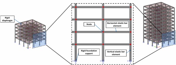
| Slabs | As a rigid diaphragm and non-contributing to the flexural stiffness of the beams |
| Columns and beams modelling position | Central axis |
| Columns and beams type | Linear elastic bar elements (Bernoulli formulation) |
| Joints stiffness modelling | No |
| Cracked stiffness of the concrete | E∙A/2;E∙I/2; G∙J/2 As proposed in EN 1998-1:2004 and FprEN 1998-1-1:2024 |
| Masses | (a) Masses of the slabs, other permanent loads and live-loads with the quasi-permanent value, were assumed uniformly distributed in the floors |
| (b) masses of the frame elements (beams and columns) were considered automatically by the software (distributed along the axis of the elements) | |
| Bending moments redistribution | No redistribution has been made |
| Beam to column connection | concentric |
| Accidental eccentricities | Taken into account |
| Second-order effects P-Δ | Taken into account, calculated by the FE software |
| Infills | Stiffness and strengths were non-considered. Their weight was included in the vertical self-weight and masses |
| Support at the foundation level | Restrained in all directions |
To provide a visual representation of the finite element (FE) model used in the analysis of the 5 and 10-storey buildings, a schematic structural model is presented in Fig. 2.
 Fig. 2
3.2. Seismic action
The capacity of structural systems to withstand seismic actions in the non-linear range often allows for their design to be based on seismic forces smaller than those required for a linear elastic response. To avoid the need for explicit inelastic structural analysis during the design phase, the structure's ability to dissipate energy through the ductile behaviour of its elements and other mechanisms is considered by performing an elastic analysis based on a reduced response spectrum with respect to the elastic one. This reduction is achieved by introducing the behaviour factor q, whose definition depends on the type of structure and its regularity in plan and elevation.
3.2.1. Regularity in plan and elevation
The criteria for regularity in plan were verified according to EN 1998–1:2004[2]. The slenderness of the building corresponds to λ = 1,0, since the building is square in the horizontal plane, and therefore λ is smaller than 4,0. The ratio between the torsional radius and the radius of gyration of the floor mass at each storey level in both horizontal directions (ri/ls) ranges between 1,18 and 1,25. Since this ratio surpasses 1,0, the corresponding criterium is satisfied. Additionally, the buildings possess double symmetry, ensuring that the centre of gravity aligns with the centre of rigidity. This results in an eccentricity (e0) of zero in the orthogonal directions. Consequently, the specified criterion of e0 ≤ 0,3∙ri is also fulfilled. Since these three conditions are met, the buildings are categorised as regular in plan in both directions.
The buildings also meet the qualitative criteria to be considered regular in elevation according to EN 1998–1:2004[2]. The prEN 1998–1-1:2023[3] refers to a quantitative criterion preconizing that “both the lateral stiffness and the mass of the individual storeys remain constant or decrease gradually by no more than 20% relative to the storey below, without abrupt changes, from the base to at least one storey below the top storey”. Since interstorey stiffness and mass of the individual storeys decrease gradually by no more than 10%, the buildings are classified as regular in elevation.
To categorize a building as having "torsional flexibility", the verification involves the comparison of two uncoupled vibration frequencies: ωθ/ωx, and ωθ/ωy. Here, ωx and ωy denotes the uncoupled angular natural frequencies of the system in the x and y directions, respectively, while ωθ represents the uncoupled circular natural frequency of torsional vibration. If the ratios ωθ/ωx, and ωθ/ωy exceed 1,0, the response primarily exhibits translational characteristics, classifying the structure as non-torsionally flexible. Conversely, if ωθ/ωx, and ωθ/ωy are below 1, the response is predominantly influenced by torsional behaviour. In the current study, the angular frequency ratios ωθ/ωx, and ωθ/ωy exceed 1,0, thus categorizing the structures under consideration as non-torsionally flexible.
3.2.2. Behaviour factor applied in the analysis
To build up the design spectra for elastic analysis, and regarding the structural systems in question, the behaviour factor q and its components are defined per EN 1998–1:2004[2] and prEN 1998–1-2:2023[3] for structures regular in plan and elevation.
The present work considers the analysis of the DCM ductility class, which is preconised in EN 1998–1:2004[2]. For the structures of interest for the current work, i.e., multistorey and multi-bay regular frame structures, the behaviour factor adopted is the basic value of the behaviour factor, defined by expression (1):(1)where α1 is the value by which the horizontal seismic design action is multiplied in order to first reach the flexural resistance in any member in the structure, while all other design actions remain constant, and αu is the value by which the horizontal seismic design action is multiplied, in order to form plastic hinges in a number of sections sufficient for the development of overall structural instability, while all other design actions remain constant. For multistorey, multi-bay frames the ratio∙αu/α1 takes the value of 1,3, therefore q0= 3,9. The upper limit value of the behaviour factor q is expressed as depicted in expression (2):(2)where kw is the factor reflecting the prevailing failure mode in structural systems with walls. The parameter kw takes the value of 1,0 for frame systems. Considering the aforementioned, the adopted behaviour factor (q) assumes a value of 3,9.
The new generation of Eurocode 8, prEN 1998–1-2:2023[3], introduces a behaviour factor composed by the product of the partial behaviour factor components qS, qR, and qD. The parameter qR is the behaviour factor component accounting for overstrength due to the redistribution of seismic action effects in redundant structures, qS is the behaviour factor component accounting for overstrength due to all other sources, and qD is the behaviour factor component accounting for the deformation and energy dissipation capacity.
Regarding prEN 1998–1-2:2023[3], to build up the design spectra for elastic analysis, and regarding the regular structural systems under analysis herein, the behaviour factor and its components for multistorey, multi-bay moment resisting frames are presented in Table 6.
| Structure | qR | qS | qD | q=qR∙qS∙qD |
|---|---|---|---|---|
| DC2.50.5 | 1,3 | 1,5 | 1,3 | 2,5 |
| DC3.50.5 | 2,0 | 3,9 | ||
| DC3.75.5 | 2,0 | 3,9 | ||
| DC2.50.10 | 1,3 | 2,5 | ||
| DC3.50.10 | 2,0 | 3,9 | ||
| DC3.75.10 | 2,0 | 3,9 |
3.2.3. Response spectra
The seismic action is defined according to EN 1998–1:2004[2]. For structures of ordinary importance, the recommendation in EN 1998–1:2004[2] is for a seismic action for (local) collapse prevention with a 10% exceedance probability in 50 years (i.e. mean return period of 475 years). For the present study, the type 1 elastic and the design spectra for elastic analysis are drawn up according to EN 1998–1:2004[2] for ground type B and an importance class II with an importance factor γI= 1,0. Table 7 shows the values of the parameters describing the elastic response spectra (ξ = 5%) for the structures under analysis.
| Structure | Ductility Class | Sα (m/s2) | ag (m/s2) | q |
|---|---|---|---|---|
|
DCM.50.5 DCM.50.10 |
DCM | 5,00 | 1,67 | 3,9 |
|
DCM.75.5 DCM.75.10 |
7,50 | 2,50 | ||
|
DC2.50.5 DC2.50.10 |
DC2 | 5,00 | 1,67 | 2,5 |
|
DC3.50.5 DC3.50.10 |
DC3 | 5,00 | 1,67 | 3,9 |
|
DC3.75.5 DC3.75.10 |
7,50 | 2,50 |
Table 7 refers to the maximum response spectral acceleration at the constant acceleration range (Sα) and the different values for behaviour factor q. For reliability differentiation, EN 1990:2002[11] establishes consequences classes (CC), which define quantitatively the consequences of failure or malfunction. A Consequence Class CC2 is assumed, defined as having medium consequences for the loss of human life, with considerable impacts on economic, social, and environmental aspects. For the consequence class CC2 the design spectrum does not require amplification related to reliability differentiation.
3.3. Structural safety verifications to limit states
Deformation-related criteria are prescribed for all types of buildings in EN 1998–1:2004[2] and prEN 1998–1-2:2023[3]. However, in the case of tall RC moment-resistant frames, their flexibility often governs the design, and they are subjected to additional criteria. Eurocode 8 sets out safety verification criteria for the Ultimate Limit State (ULS) according to EN 1998–1:2004[2] and for Significant Damage Limit State (SD) according to prEN 1998–1-2:2023[3]. These safety criteria include the control of second-order effects, limitation of interstorey drift (ISD), and control of the global plastic mechanism (resulting from capacity design in flexure). It should be noted that EN 1998–1:2004[2] considers only the serviceability condition as a Damage-Limitation Limit State (DL) for controlling ISD, whereas prEN 1998–1-2:2023[3] considers both DL and SD limit states.
3.3.1. Control of second-order effects
The second-order effects (P-Δ), which are associated with ULS effects, are specified through an interstorey drift sensitivity coefficient (θ) as shown in Eq. (3) based on EN 1998–1:2004[2]:(3)
According to prEN 1998–1-2:2023[3], second-order effects (P-Δ) are associated with SD limit states and are defined by Eq. (4):(4)where Ptot and Vtot are the total cumulative gravity load and seismic shear, respectively, at the storey under consideration; hs and h are the storey height.
EN 1998–1[2] and prEN 1998–1-2[3] both specify that when the interstorey drift sensitivity coefficient (θ) has a value between 0,1 and 0,2, an approximate adjustment for P-Δ effects can be made by increasing the seismic forces used in the analysis by a factor of 1/(1-θ). On the other hand, when θ is between 0,2 and 0,3, a second-order analysis is necessary.
3.3.2. Limitation of the interstorey drift ISD
In a current design with a force-based approach, the interstorey drifts are the product of elastic interstorey drift from analysis and the behaviour factor q. According to EN 1998–1:2004[2], the interstorey drift verification is included regarding the serviceability condition as damage-limitation (DL). The prEN 1998–1-2:2023[3] considers two limit states for the verification, the damage limitation (DL) and the significant damage limit state (SD).
Since the seismic analysis in a force-based approach is linear-elastic and based on the design response spectrum, the elastic spectrum with 5% damping divided by the behaviour factor q is used. The values of the displacements (ds) to be used in the verification are calculated from the analysis (de) and multiplied by the behaviour factor q, as shown in Eq. (5):(5)
The design interstorey drift dr, is calculated as the difference of the average lateral displacements’ ds induced by the reduced seismic action at the top and bottom of the storey under consideration as depicted in Eq. (6):(6)
EN 1998–1:2004[2] defines the limit of interstorey drift ratio (IDR) according to Eq. (7):(7)where Κ is the coefficient that accounts for the sensitivity of ancillary elements to interstorey drift, h is the interstorey height, and ν is the reduction factor which considers the lower return period of the seismic action associated with the damage limitation requirement. Table 8 presents the IDR limits according to EN 1998–1:2004[2] and assuming ν = 0,5.
| Type | IDR limit (K/ν) at DL [%] |
|---|---|
| Buildings having non-structural elements of brittle materials attached to the structure | 1,00 |
| Buildings having ductile non-structural elements: | 1,50 |
| Buildings having non-structural elements fixed in a way so as not to interfere with structural deformations or without non-structural elements | 2,00 |
The prEN 1998–1-2:2023[3] presents a similar formulation, where λNS is the coefficient accounting for the sensitivity of ancillary elements to interstorey drift, the subscript LS refers to limit state and hs has the same meaning as h.(8)
The IDR limits as per prEN 1998–1-2:2023[3] are presented in Table 9.