Highlights
-
•
Underwater noise due to non-symmetric forces.
-
•
Underwater noise from inclined piles.
-
•
Noise around the ring frequency.
Abstract
Offshore wind energy holds significant promise as a solution in the energy transition. However, installing offshore pile foundations can generate substantial levels of underwater noise, posing potential risks to marine life. This paper examines the influence of asymmetric impact forces and pile inclination on producing underwater noise and seabed vibrations based on cases of a small- and large-diameter monopile. The study focuses on scenarios involving inclined and eccentric forces and tilted piles. The analysis reveals that non-symmetrical conditions significantly impact the sound pressure levels around the ring frequency of the pile due to various noise generation mechanisms. However, it is observed that the vertical component of the impact force predominantly contributes to the generation of underwater noise, primarily due to its considerably higher amplitude.
Keywords
Underwater noise
Pile driving
Asymmetric noise field
Inclined pile
1. Introduction
Offshore wind energy is an essential renewable energy source, but the construction of offshore wind turbines can have significant environmental impacts. The increasing size of monopiles to support the increasingly large offshore wind turbines presents several challenges. According to Sunday and Brennan (2021), these challenges include assessing and controlling construction peak noise levels, managing noise exposure levels, addressing excessive pile inclination, and preventing plastic deformation of the thin-shell pile head caused by the more significant hammer force required for pile driving.
High underwater sound levels generated during the installation of monopile foundations with impact pile driving can disturb the behaviour of marine life several kilometres away from the site (Dahl et al., 2014, Madsen et al., 2006), and it can lead to physical harm and even fatal injury of underwater mammals near the driving site (Southall et al., 2019).
Though more silent pile driving methods are under development (Tsetas et al., 2023), accurate predictions are required to forecast the underwater noise field caused by offshore pile driving. As a result, several models have been developed in the past decade. Early noise prediction models employed an acoustic fluid representation of the sediment, focussing on the radiation of the Mach wave (Reinhall and Dahl, 2011, Lippert and Lippert, 2012, Zampolli et al., 2013). Second-generation models included an elastic description of the sediment (Tsouvalas and Metrikine, 2014, Göttsche et al., 2015, Fricke and Rolfes, 2015, Jiang et al., 2022).
Peng et al. (2021a) improved the modelling of the propagated sound field using Green’s functions, while Lippert et al. (2018) presented a simplified approach based on transmission losses. Last, semi-empirical models are developed, providing scaling laws on hammer properties, pile dimensions and water depth (von Pein et al., 2022).
However, several open challenges remain, including developing models suitable for vibratory pile driving, noise mitigation systems, uncertainty analysis and non-symmetric noise fields (Tsouvalas, 2020). Recently, steps have been taken to understand noise generated during vibratory pile driving (Molenkamp et al., 2023), model air-bubble curtains to mitigate high noise levels (Peng et al., 2021b) and propagate mitigated noise fields (Jestel et al., 2021).
Inclined forces have earlier been addressed in Tsouvalas and Metrikine (2013)and Deng et al. (2016) via simplified acoustic models representing soil with springs. However, quantifying the effect on noise emission has not been systematically studied. Wilkes and Gavrilov (2017) modelled and studied the sound radiated from impact-driven raked piles, where the raked piles are installed under an angle of 14.5° and have significantly smaller dimensions than monopile foundations. The soil is modelled herein as an acoustic fluid, disregarding pile-soil interaction.
This paper focuses on the effect of unintended non-symmetric sound fields generated during impact piling of monopile foundations for wind farms. Specifically, the cases with an inclined force, an eccentric force and a tilted pile are studied. Since measurements sometimes show substantial azimuthal variation of the acoustic field, the impact of non-symmetries in the force and geometry on noise levels should be investigated.
This paper quantifies and explains the effect of non-symmetric force excitations on underwater acoustics noise fields, focusing on inclined forces, eccentric forces, and an inclined pile. The effects are studied using frequency domain analysis based on the case of a small- and large-diameter monopile. The paper provides physical explanations of the results and offers advice for engineering applications.
A COMSOL Multiphysics® FEM model is built to model the pile and its vicinity, predicting sound pressure levels, sound exposure levels, and peak pressures in the frequency domain. The model description is provided in Section 2, containing governing equations and modelling assumptions. Section 3 examines two case studies on installing a small and large-diameter monopile. The small pile is modelled to compare conclusions with Deng et al. (2016) and can represent a pin pile. The large-diameter monopile described by Peng et al. (2021a) is modelled to verify the conclusions on a practical scale. Lastly, the conclusions are given in Section 4.
2. Model description
A model is created in COMSOL Multiphysics® (2022) to evaluate the non-symmetric excitation forces. COMSOL Multiphysics® is a finite element package often used for near-field noise generation, i.e. the first tens of meters. In the Compile benchmark case (Lippert et al., 2016), four out of seven participants used COMSOL Multiphysics® as a noise generation model, and it has been validated against data by and validated against measurements (Zampolli et al., 2013, Reinhall and Dahl, 2011). The disadvantage of a finite element package is the computational expenses; therefore, separate models are used for far-field propagation, i.e., hundreds of meters to kilometres, and the software is unsuitable for uncertainty analysis. The near-field results can be propagated with different methods, such as the wave number integration, normal modes or parabolic equation method, to predict the acoustic far-field. To reduce computational costs, mode extension around the circumferential azimuth is used, reducing the discretization from 3D to 2D for the cases of inclined and eccentric forces. The tilted pile is modelled in 3D with significant computational costs.
The model geometry presented in Fig. 1 shows the model domains and boundaries. indicates the fluid domain, modelled with acoustic elements and is described by: (1)with pressure field , being a monopole domain source and contains dipole domain sources. The parameters , and are the fluid density, fluid wave speed and angular frequency, respectively. The pile and soil domains, and are modelled with solid elements described by: (2)with stress vector , displacement vector and force vector containing the external hammer forces () at the top of the pile; is the solid density.
 Fig. 1
The 2D axisymmetric model has a symmetry axis at , i.e. boundary . Boundaries and are prescribed by Sommerfeld’s radiation condition and modelled in COMSOL Multiphysics® as Cylindrical Wave Radiation and Low-reflecting boundaries, respectively. The sea surface, , is modelled as a pressure release boundary, i.e. . The interfaces between pile and fluid, and soil and fluid, and are modelled with Acoustic-Structure Boundary conditions, prescribing continuity of normal displacements and pressure and allowing no shear stresses. The pile-soil interface needs no specific description since both are modelled with the same type of elements with different material properties. Pile and soil are connected monolithically, i.e. no pile slip or separation is allowed relative to the soil. The model is truncated five m below the bottom of the pile and at and m for the small and large piles, respectively. A frequency-dependent adaptive mesh size is used that guarantees five elements per wavelength.
The 3D model is similar to the 2D axisymmetric model, but the entire 3D domain is modelled, and the axis of symmetry is removed. The pile is rotated around the -axis halfway through its length. A symmetry plane boundary is introduced at . The domain is truncated at m to reduce computation costs as computational costs grow exponentially with an extended domain in . The domain truncations are considered sufficient (compared to 6.5 m in Wilkes and Gavrilov (2017)) to describe the noise generation mechanism, whereas propagation can be obtained by other than FEM methods.
This paper considers two types of non-symmetric forces: An inclined force and an eccentric force. The relation between the vertical and horizontal comments of the force, and , are found via: (3)with being the time-independent angle of inclination. During installation, the maximally allowable tilt at the seabed level is 0.25 degree (Veritas, 2004), and due to modern motion-compensated pile grippers, the monopile installation happens almost vertically. This paper assumes an angle of three degrees, which is assumed to be a practical upper limit. Therefore, the is approximately 5% of .
The eccentric force induces a moment around the -axis next to the vertical force. The moment is found via: (4)with a relative eccentricity and being the absolute eccentricity. This paper assumes that the eccentricity is proportional to 5% of the pile’s radius, again assuming to be an extreme case. These forces translate to distributed loads on top of the pile per azimuthal mode number via: (5)(6)(7)(8) The effect of each force component is examined in the case studies hereafter.
The case with the tilted pile assumes a tilt of three degrees; this limit case is reviewed to find pressure level differences and seabed vibrations on both sides of the pile. The force is assumed to be in parallel with the pile.
3. The non-symmetric noise field
The non-symmetric noise field is examined for the case of a small- and large-diameter monopile taken from Deng et al. (2016) and Peng et al. (2021a), respectively. In both cases, the effect of non-symmetry of noise is examined; the conclusions are compared for the small monopile with those of Deng et al. (2016). The physical explanation of the noise generation is accomplished based on the large monopile case. A frequency domain analysis is performed, and the time domain response is retrieved using an inverse FFT. To quantify the noise emission, the sound exposure levels, , sound pressure levels, and the peak sound pressure level, are calculated by the definition of ISO (2017): (9)(10)(11) in which real mean square pressure and peak pressure . The reference pressure µPa for underwater acoustic calculations. The force transfer functions are defined by: (12)with being , or .
3.1. Small-diameter pile
Deng et al. (2016) show the case of a two meter diameter monopile of 28 m length partially driven in the soil. Piles of these dimensions are relatively small in the current offshore wind industry but are used for jacket foundations. The corresponding ring frequency is Hz. The water depth is shallow, resulting in a cut-off frequency of the first propagating mode of about 47 Hz. Further material and geometry properties are summarized in Table 1.
| Parameter | unit | |
|---|---|---|
| Pile Youngs modulus [] | 210 | GPa |
| Pile Poison’s ratio [] | 0.28 | – |
| Pile density [] | 7800 | kg m-3 |
| Structural damping [] | 0.002 | – |
| Pile length [] | 28 | m |
| Pile radius [] | 1 | m |
| Pile thickness [] | 0.02 | m |
| Pile soil penetration | 10 | m |
| Fluid wave speed [] | 1500 | m s-1 |
| Fluid density [] | 1000 | kg m-3 |
| Water depth | 8 | m |
| Soil Youngs modulus [] | 50 | MPa |
| Soil Poison’s ratio [] | 0.40 | – |
| Soil density [] | 1600 | kg m-3 |
The external load on top of the pile is described by: (13)with MN m-1 and ms. Fig. 2a shows the time signature of the applied force while Fig. 2b shows the amplitude spectrum of the force. Frequencies up to 2500 Hz with a stepsize of 1 Hz are included in the frequency response analysis.
 Fig. 2
The absolute value of the frequency response transfer functions in Fig. 3 shows the pressure levels at m and . The transfer functions are plotted on a decibel scale after substitution in Eq. (10). The transfer function shows almost no sound propagation below 37.5 Hz, the cut-off frequency of the fluid and around 857 Hz, the ring frequency of the pile.
 Fig. 3
The ring frequency of the pile indicates the frequency at which the wavelength is equal to the circumference of the pile. The modal density around this frequency is high (Leissa, 1973). The vertical group velocity of waves close to the ring frequency is almost zero. Thus, almost no energy propagates downwards the pile from the hammer impact location. This is further discussed in Section 3.2.
The sound waves generated by a horizontal force or a moment do not propagate below the fluid’s cut-off frequency but propagate at the pile’s ring frequency, while the ring frequency corresponds solely to the axisymmetric shell. The absolute value of the transfer functions of a horizontal load is significantly higher than those of a vertical load. Nonetheless, the sound pressure levels, shown in Fig. 3b, are significantly lower compared to the vertical load since the amplitude of the non-symmetric force components is significantly lower than the vertical component of the force, with the ring-frequency as the only exception.
Deng et al. (2016) concludes that the non-uniformity of the load is strongest around the ring frequency for an inclined load. The results presented here agree with that, and the same conclusion holds for a force moment on top of the pile.
Fig. 4 compares the peak pressure and sound exposure levels of the inclined and eccentric loads with the vertical load. Despite different approaches, the sound exposure levels and peak pressure levels compare well to Deng et al. (2016) for the symmetric force, i.e. dB and dB at m. The levels are taken at the worst azimuth; thus, either or dependent on the phase of the forces. As expected from the sound pressure levels, the sound exposure and peak pressure levels are all very close. Especially, the sound exposure levels seem uninfluenced, but the peak pressure levels are all within dB as well.
 Fig. 4
Deng et al. (2016) state that underwater noise measurements at one location around the circumference are insufficient when the impact force has a significant non-symmetric component. This work supports this statement if one is interested in detailed frequency content around the ring frequency. The differences around the circumference are insignificant if one is interested in more general sound levels, such as the peak pressure and sound exposure levels. Other uncertainties, such as bathymetry variation or seabed composition with strong azimuthal dependence, likely influence sound variations around the azimuthal direction more.
3.2. Large diameter pile
The effects of non-symmetric forces for a large-diameter monopile are studied based on the case of a windmill installed in the German North Sea presented by Peng et al. (2021a). First, the case of the pile driven as described is examined; after that, the pile penetration depth and the impact duration are changed. The pile is eight m in diameter and 76.9 m in length. The soil consists of a thin upper layer founded on the bottom sediment. The material and geometry parameters are given in Table 2. The ring frequency of the pile is Hz, and the fluid cut-off frequency is approximately Hz.
| Parameter | unit | |
|---|---|---|
| Pile Youngs modulus [] | 210 | GPa |
| Pile Poison’s ratio [] | 0.30 | – |
| Pile density [] | 7850 | kg m-3 |
| Structural damping [] | 0.001 | – |
| Pile length [] | 76.9 | m |
| Pile radius [] | 4 | m |
| Pile thickness [] | 0.09 | m |
| Pile soil penetration | 40.1 | m |
| Fluid wave speed [] | 1500 | m s-1 |
| Fluid density [] | 1000 | kg m-3 |
| Water depth | 39.9 | m |
| Soil layer compressional wave speed [] | 1560 | m s-1 |
| Soil layer shear wave speed [] | 94 | m s-1 |
| Soil layer density [] | 1670 | kg m-3 |
| Soil layer thickness | 1.5 | m |
| Soil bottom compressional wave speed [] | 1979 | m s-1 |
| Soil bottom shear wave speed [] | 349 | m s-1 |
| Soil bottom density [] | 1950 | kg m-3 |
The force on top of the pile corresponds to a hammer blow of approximately 1750 kJ and is described by: (14)The force parameters are: , , , s and s, i.e. the force plotted in Fig. 5 with the accompanying Fourier amplitude spectrum. For the analysis, frequencies up to 750 Hz are included with a step of 1 Hz. Fig. 5 shows that the described force contains less high-frequency content than the force applied on the small-diameter monopile, which justifies the upper limit frequency truncation.
 Fig. 5
Fig. 6 shows the absolute value of the transfer functions and the sound pressure levels corresponding to the case. Similar to the small-diameter monopile, negligible sound is propagated around the ring frequency of the pile due to an axisymmetric vertical load. On the other hand, the absolute value of the transfer function of the horizontal load peaks around these frequencies. This is because the modal density at the first azimuthal mode is high and contains many modes governed by shear motion. Examining the sound pressure levels in Fig. 6b, the noise generated by the horizontal or moment component of the force is significantly smaller at all frequencies except around the ring frequency. This phenomenon is the same at both small- and large-diameter monopiles.
 Fig. 6
The ring frequency explains the drop in the noise levels at axisymmetric vertical excitation, while the waves excited around the ring frequency have a vertical group velocity approaching zero. Therefore, energy cannot propagate through the pile and remains close to the hammer impact location. This can be observed by comparing the radial pile vibrations at multiple locations along the pile length around these frequencies.

Fig. 7a shows that the radial displacements peak around the ring frequency at the top of the pile due to a high modal density and little energy propagating downwards. Therefore, this peak is not observed anymore halfway through the fluid column in Fig. 7b.
The horizontal load and moment do not excite horizontal motion around the ring frequency since this mode does not exist in non-symmetric configurations. The largest radial vibrations are observed at low frequencies, where the first bending modes are located (the first between 1.4 and 8.3 Hz assuming fixed-free and free-free boundary conditions, respectively). However, the first bending modes do not cause significant sound levels, as seen in Fig. 6, while the fluid pressure is proportional to acceleration that scales quadratically with frequency.
Fig. 8 shows the time response at for each component of the force individually. It should be stressed that the scales of the horizontal and moment components are 20 times smaller than the colour scale of the vertical component. The vertical force induces a Mach-cone wave that reflects up and down, as indicated with the arrows at 0.02 s and 0.04 s. The noise generation mechanism and the angle of the Mach-cone, , are in agreement with theory (Reinhall and Dahl, 2011), with corresponding to the compressional wave speed of the pile. Furthermore, at s, Scholte interface waves are visible in the wave field.
 Fig. 8
The noise generation mechanism due to a horizontal load or moment varies from the case of a vertical load. At s, two Mach-cones are identifiable, as the arrows indicate.
The second Mach-cone is active by the slower travelling shear wave with a shorter length. The shorter wavelength is clearly observable at 0.03 s, where the positive and negative pressure levels along the pile alter more quickly than the field generated by a vertical load. It also shows that sound is radiated along a longer timespan.
The Mach-cone generated by the shear wave has an angle of , in which refers to the shear-wave velocity of the pile. The transmission loss model presented by Lippert et al. (2018) shows a relation between the propagation angle of the wave and transmission losses. The Mach waves with an angle of are expected to propagate less efficiently due to a larger number of reflections with the seabed and a smaller reflection coefficient due to a greater angle between water and soil. Therefore, at more considerable distances, the contribution of the non-symmetrical components of the noise field will be less prominent than in the near field. Depending on the water depth and the reflection coefficient of the seabed, the added transmission loss is more or less significant.
Scholte interface waves at the seabed are less prominent because the horizontally dominated pile vibrations excite Love waves. The latter does not cause noise into the fluid domain because they have no vertical component in the displacement field and contain only horizontally polarized shear waves (SH waves).
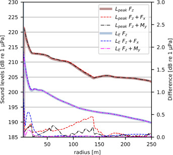
In practice, the peak pressure and sound exposure levels are usually reported and checked against noise thresholds imposed by regulators. Fig. 9 shows that the non-symmetric components do not influence noise levels at the critical azimuth ( or ). This aligns with the observations of the sound pressure levels; the horizontal load and moment only contribute around the ring frequency, and there is little energy at these frequencies. Besides that, it should be remembered that waves at a particular frequency rarely fully sum up because of a phase difference. Furthermore, it can be concluded that an inclined load causes higher noise levels than an eccentric load, though both are insignificant in this case. These conclusions can alter if the force has more energy around the ring frequency or when the system properties change. Both cases are examined hereafter.